
Beacon Machine Manufacturing Co.,ltd
 Language
 EN
 RU
 ES
 DE
 EL
 IT
 JA
 KO
 PT
 ID
 SR
 UK
 VI
 TH
 TR
 MS
 BE
 AR
EUI/EUP Bench Test Results Explained: Fuel Delivery, Response Time and Cam Box Setup
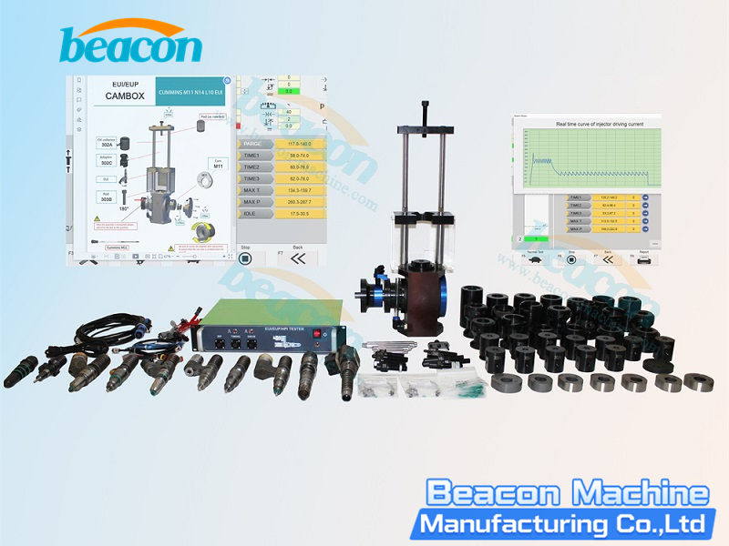
An EUI (Electronic Unit Injector) combines the pump and nozzle in one component. In an EUP (Electronic Unit Pump) system, the pump and nozzle are separate and connected by a high-pressure line. Their mounting arrangements and fuel-measurement paths therefore differ. Before reading a test report, identify the component type and full part number, then check the cam box, connections and test program. Bosch's description of UIS and UPS system design
1. Check the Test Conditions Before Reading the Results
Record the following information:
- Full part number, manufacturer and selected test program;
- Cam, adapter, clamping arrangement and fuel connections;
- Actual bench speed, fuel-supply conditions and electrical drive conditions required by the program;
- Fuel-delivery measurement method, units and measurement duration;
- Signal or sensor used for response-time measurement and the definition of that value.
The cam box provides the mechanical drive required for testing the component. Match the adapters and cam configuration to the specific application. Hartridge's EUI/EUP cam-box information also distinguishes application coverage from the corresponding test configuration.
The operating instructions for the Beacon EUS-1800 tester require the manufacturer and part number to be selected and the bench to reach the target speed before the test starts. Automatic fuel-delivery measurement requires the relevant flowmeter; check the equipment's actual configuration before use.
2. Fuel Delivery: Compare Each Test Point Under Matching Conditions
Compare fuel delivery with the corresponding operating point in the test program for the exact part number. Check speed, drive settings, fuel-supply conditions, measurement units and collection method before judging whether a value is within the specified range.
If delivery is low at several test points, first check fuel supply, bleeding, cam-box drive, mounting and the measuring channel. If these conditions are stable and only one component repeatedly falls outside the specified range, investigate that component further. A passing result at one test point does not replace the other points required by the program.
For an EUP, also check the nozzle, high-pressure connection and fuel-collection device required by the test program. EUI and EUP reports may use similar names for results; confirm the actual measurement path before comparing them.
3. Response Time and BIP: Establish What the Equipment Measures
Response time is often displayed in microseconds, but different equipment can use different start points, end points and signals. Confirm whether the report records the time from electrical drive to valve movement or identifies an injection event through another sensor.
In one Volkswagen unit-injector system, the control unit identifies valve closing from a knee in the solenoid-current curve and calls this point BIP. That definition applies to the system described in the training material. When reading a BIP field on another EUI/EUP tester, check its test program and measurement instructions. Volkswagen pump-injector system training material
If the response reading is abnormal, first recheck the part number and test program, then inspect harness contact, drive signal, cam-box speed and response-measurement connection. Repeat the test under the same conditions before applying the part-specific standard.
4. Check Electrical and Leakage Results Separately
Resistance and inductance checks can help identify some electrical faults. They cover electrical condition only; fuel delivery, response and leakage each require the checks specified by the test program.
If the program includes a return-flow or leakage item, record where the fluid is collected, how long the test runs and the component's operating state. Check connectors, fixtures and seals first, then apply the limit for the exact part number. Caterpillar lists fuel delivery, timing, peak injection pressure and assembly leakage as separate end-of-line checks for its remanufactured injectors. A complete assessment draws on multiple results. Caterpillar injector testing information
5. How to Investigate Common Result Patterns
| Observation | Check first |
|---|---|
| Several components show low delivery under the same test condition | Fuel supply, bleeding, speed, cam-box setup and measuring channel |
| Only one component repeatedly falls outside the range | Its mounting, connections and part-specific test results |
| Fuel delivery meets the requirement, but the response reading is abnormal | Definition of the response field, harness, drive signal and measurement connection |
| Fuel-delivery and response readings are both unstable | Stability of speed, fuel supply, connectors, fixtures and test conditions |
| A return-flow or leakage item in the program is abnormal | Collection point, connectors and seals, and the limit for that component |
This table organizes the order of checks. Make the final pass/fail decision using the test program and limits for the exact part number.
Conclusion
An EUI/EUP report useful for a repair decision should retain the part number, test program, cam-box and adapter configuration, actual speed, fuel-supply and drive conditions, delivery at each test point, the measurement definition of any response item and repeated results. Confirm the test conditions before judging component condition to reduce misdiagnosis caused by a wrong program or connection.
Related products

CR318-PRO HEUI High Pressure Common Rail Injector Test Bench - Dual Motor 5.5KW+2.2KW
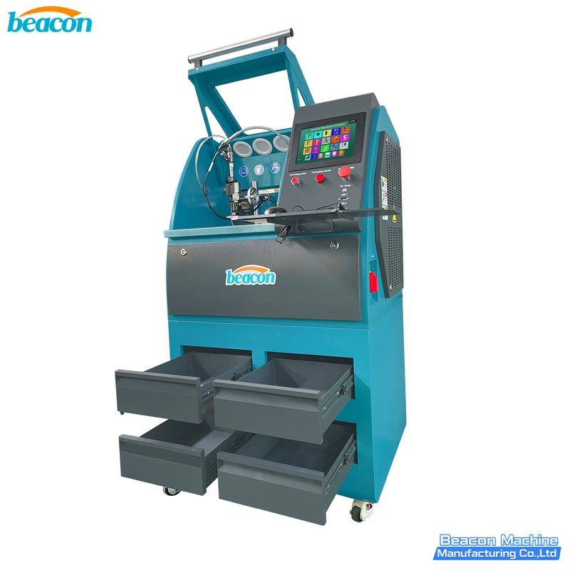
EPS206 PLUS Common Rail Injector Test Bench | Piezo & Coding
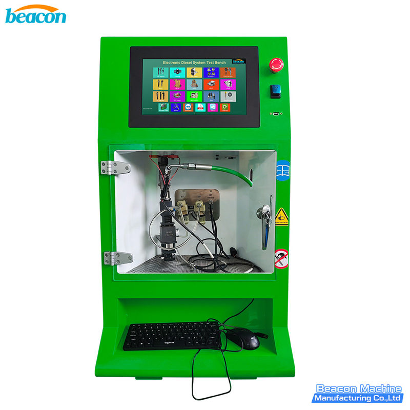
EPS212 Common Rail Injector Test Bench

CR918-PRO Full Function Common Rail HEUI EUI EUP Test Bench with 4 Tanks
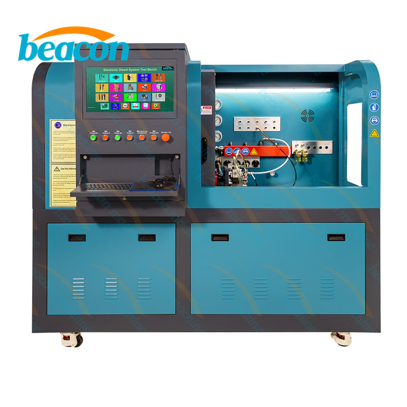
Beacon CR819S All-Function Common Rail Injector, Pump, EUI/EUP & HEUI Test Bench
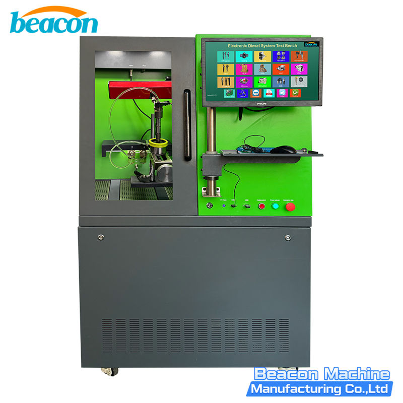
Beacon BC200-PRO Common Rail Injector Test Bench

Beacon EPS106 Common Rail Injector Tester – Professional Test Bench for Solenoid & Piezo Injectors
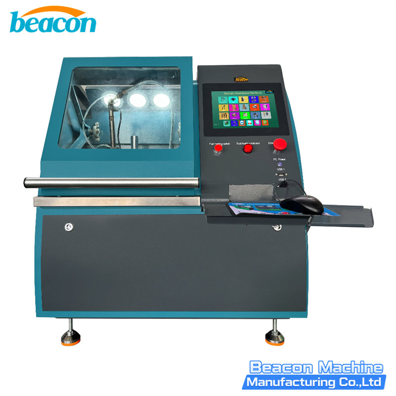
Beacon EPS206-PRO Common Rail Injector Test Bench | Coding & Piezo Testing
Beacon Machine Manufacturing Co.,ltd
Quick Links
contact
WhatsApp: +86-13570429157
Tel / Wechat: 0086-13570429157
Email: ellenzhang@beacon-machine.com
Add: High Technology Industrial Park of Taian city,Shandong province,China


quick order
We will reply to your email within 2 hours