Beacon Machine Manufacturing Co.,ltd
 Language
 Cummins Injector Debugging Guide: Solutions to Boost Engine Performance
The 2000kg ultra-high pressure injector jointly created by Cummins and Scania—the Cummins XPI leak-free nozzle (common models include 7072, 7475, and 9204), provides a one-stop solution for engine difficulties. For premium replacement parts, you can explore high-quality Cummins XPI injectors to ensure optimal performance.
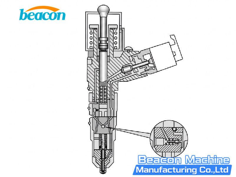
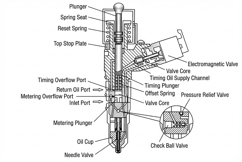
▲ Key Injector Components and Test Points
The Cummins injector mainly consists of three parts: the armature assembly, the needle valve assembly, and the nozzle head. The nozzle head contains the pressure cap, nozzle, oil needle, and spring. The armature assembly consists of precise components like the pressure cap, solenoid valve, armature core, and shims. The needle valve assembly includes the intermediate sleeve, upper/middle/lower valve bodies. Additionally, it is equipped with a solenoid valve adjusting screw and spring.
Understanding the test points is crucial. The test points for the injector include TPO (exhaust and warm-up), TP1 (idle), TP2 & TP3 (full load), TP4 (partial load), and TP5 (pre-injection). These points are directly related to engine performance, fuel economy, and emissions.
▲ Debugging Focus
During the debugging process, special attention must be paid to the adjustment of the armature lift shim and the fine-tuning of the solenoid valve spring. Turning the solenoid valve spring screw counterclockwise reduces the injection volume, while turning it clockwise increases it (allows 45-degree micro-adjustments). After debugging, apply glue and dry under UV light for 5 minutes.
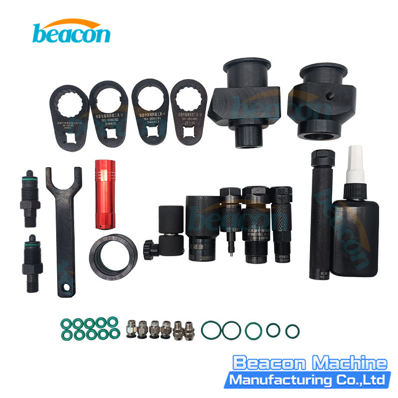
▲ Installation Steps & Precautions
- Before installation, loosen the nozzle cap, then use a special tool to remove the upper solenoid valve part.
- When assembling, install the nozzle first, then the solenoid valve. The tightening torque for the nozzle cap must be 70-75N·m. The intermediate sleeve torque should also be within 70-75N·m.
- Armature lift adjustment: The lift should be set to 50um and measured precisely during assembly.
- After adjusting the lift, further tighten or loosen the solenoid spring screw to micro-adjust the main injection volume (TP2 & TP3), and replace parts if necessary.
- Ensure the flexibility of all components, such as the fit between the nozzle and valve rod. Clean all parts thoroughly before assembly.
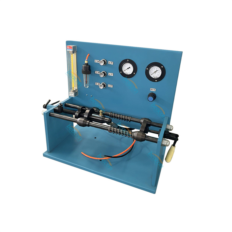
- After installation, perform equipment testing. Listen to the solenoid valve sound, then observe the actual rail pressure to judge the sealing of the upper valve ball.
- If the actual rail pressure drops too fast during testing, the small ball or upper valve may be worn and needs replacement.
- Even if the test injection volume is normal, if there is a pressure-maintaining problem, it is considered unqualified and must be handled, as the engine will be hard to start.
Beacon Machine Manufacturing Co.,ltd
Quick Links
contact
WhatsApp: +86-13570429157
Tel / Wechat: 0086-13570429157
Email: ellenzhang@beacon-machine.com
Add: High Technology Industrial Park of Taian city,Shandong province,China


quick order
We will reply to your email within 2 hours