Beacon Machine Manufacturing Co.,ltd
 Language
 Do You Understand the Working Process of the Injector? This Article Tells You.
Working Process:
The injection process of the Pump Injector can be divided into two stages: pre-injection and main injection. It can also be detailed into five processes: pre-injection, end of pre-injection, main injection, end of main injection, and oil intake of the high-pressure chamber. The injection timing and injection quantity are jointly controlled by the auxiliary plunger, injection needle valve, injection needle valve return spring, injection needle valve damper, and the solenoid control valve.
(1) Pre-injection
When the straight section of the cam contacts the rocker arm, the electronic control system supplies power to the solenoid control valve, causing the solenoid needle valve to move to the left, cutting off the passage between the high-pressure chamber and the low-pressure oil channel. At the same time, the pump plunger moves downward under the action of the rocker arm, overcoming the force of the plunger return spring, causing the oil pressure in the high-pressure chamber to rise rapidly. When the oil pressure rises to 18 MPa, the upward thrust generated by the fuel on the middle cone surface of the injection needle valve becomes greater than the pre-tightening force of the needle valve return spring, lifting the injection needle valve and starting the pre-injection.
(2) End of Pre-injection
After the pre-injection starts, the injection needle valve continues to move upward. When the cam rotates through 1/3 of the injection stroke, the lower end of the injection needle valve damper enters the damper hole. The fuel at the top of the injection needle valve can only flow into the return spring chamber through a tiny gap. Thus, a so-called "hydraulic cushion" is formed at the top of the injection needle valve, preventing it from continuing to move upward and restricting the pre-injection quantity. As the pump plunger continues to move downward, the oil pressure in the high-pressure chamber continues to rise. When the oil pressure reaches a specified value, the auxiliary plunger moves downward under the action of high-pressure fuel, causing the volume of the high-pressure chamber to suddenly increase, and the fuel pressure drops instantly.
At this time, the upward thrust on the middle cone surface of the injection needle valve decreases, and the injection needle valve resets under the action of the return spring (whose tension increases due to compression by the auxiliary plunger), ending the pre-injection.
(3) Main Injection
After the pre-injection ends, the pump plunger continues to move downward, causing the oil pressure in the high-pressure chamber to rise rapidly. When the oil pressure rises to be greater than the pre-injection pressure (30 MPa), the injection needle valve moves upward, and the main injection begins. Since the fuel pressure in the high-pressure chamber rises extremely fast, the oil pressure will continue to rise to about 205 MPa.
(4) End of Main Injection
When the electronic control system stops supplying power to the solenoid control valve, the solenoid needle valve moves to the right under the action of its return spring, connecting the high-pressure chamber with the low-pressure oil channel. At this time, the fuel in the high-pressure chamber flows to the low-pressure oil channel through the solenoid control valve, and the fuel pressure drops. The injection needle valve resets under the action of its return spring, and the auxiliary plunger closes the oil passage between the high-pressure chamber and the needle valve return spring, ending the main injection.
(5) High-Pressure Chamber Oil Intake
When the descending section of the cam contacts the rocker arm, the pump plunger moves upward under the action of its return spring, creating a vacuum in the high-pressure chamber due to the volume increase. At this time, the fuel in the low-pressure oil channel (connected to the oil inlet pipe) flows into the high-pressure chamber through the solenoid control valve until it is full, preparing for the next injection.
Related products
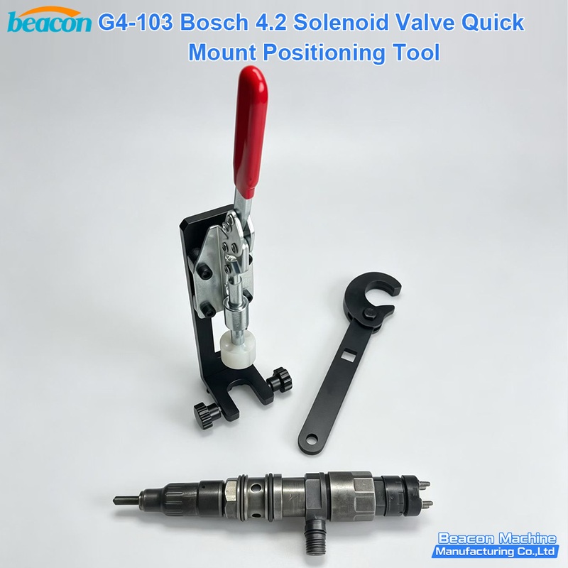
G4-103 Bosch 4.2 Solenoid Valve Quick-Positioning Installation Tool - Diesel Injector Service Tool

IART02 Injector Dedicated Tester - Injector Pressure Voltage Inductance Diagnostic Tool
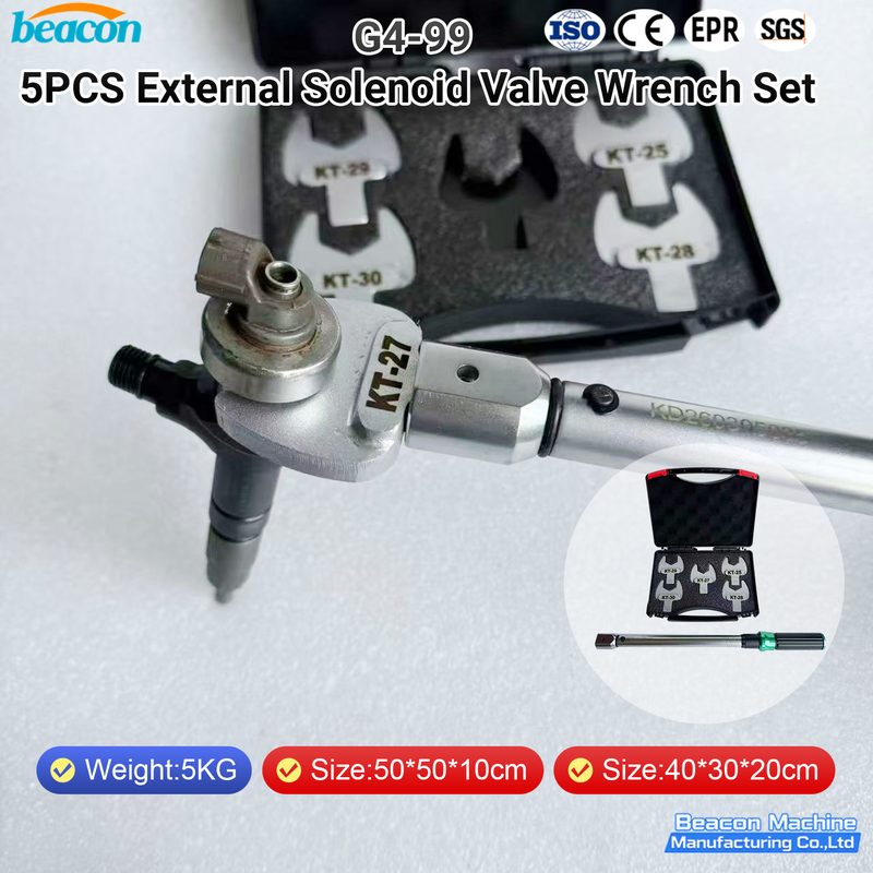
G4-99 5pc External Solenoid Valve Wrench Set - Diesel Injector Service Tool
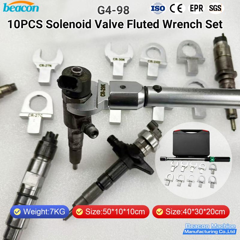
G4-98 10pc Solenoid Valve Scalloped Wrench Set - Diesel Injector Service Tool
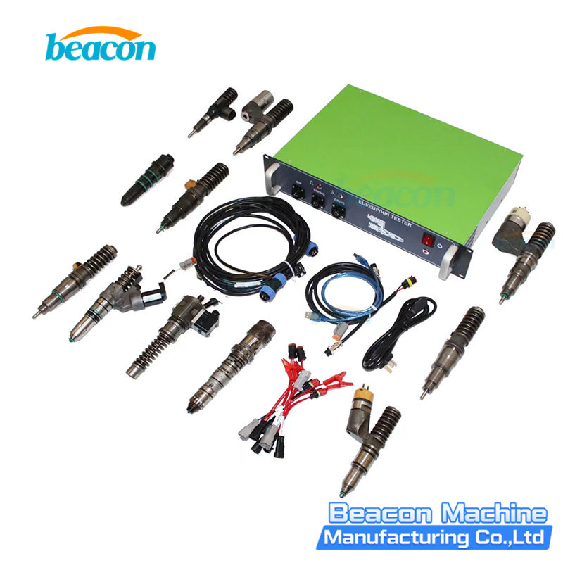
EUS-1800 EUI EUP HPI Tester for Bosch Cummins Caterpillar Delphi with Cam Box
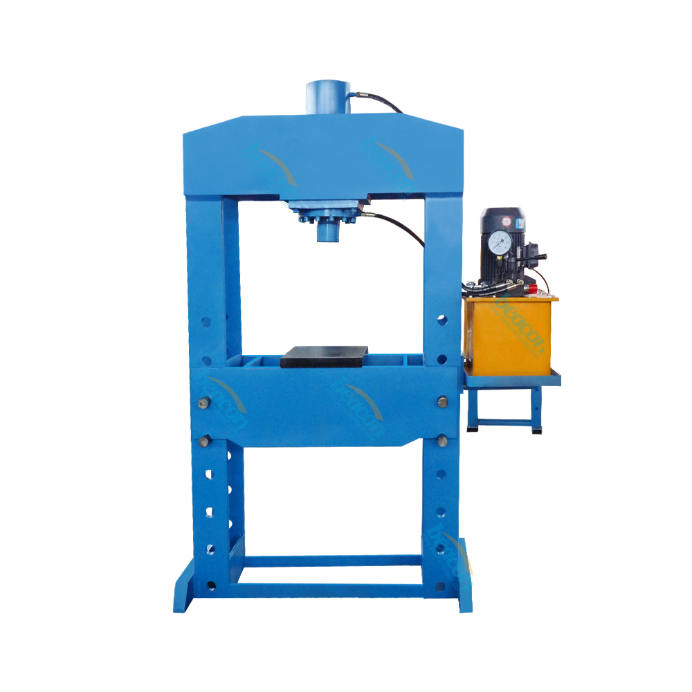
Beacon BT150 Hydraulic Press Machine For Stretching Bending And Punching Vertical Press Machine
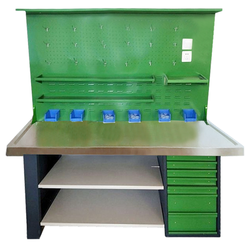
GT-F Electronic Workstation Repairing Anti-static Electrical Workbench Watchmakers Table Electronic Work Bench
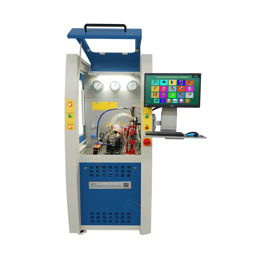
Beacon CR1027 High Pressure Common Rail Electronic Control System Comprehensive Machine Diesel Injector Pump Test Bench
Beacon Machine Manufacturing Co.,ltd
Quick Links
contact
WhatsApp: +86-13570429157
Tel / Wechat: 0086-13570429157
Email: ellenzhang@beacon-machine.com
Add: High Technology Industrial Park of Taian city,Shandong province,China


quick order
We will reply to your email within 2 hours