
Beacon Machine Manufacturing Co.,ltd
 Language
  EN
EN RU
RU ES
ES DE
DE EL
EL IT
IT JA
JA KO
KO PT
PT ID
ID SR
SR UK
UK VI
VI TH
TH TR
TR MS
MS BE
BE AR
ARHow Calibration Shims Affect AHE, Air Gap, Needle Lift and Injection Quantity
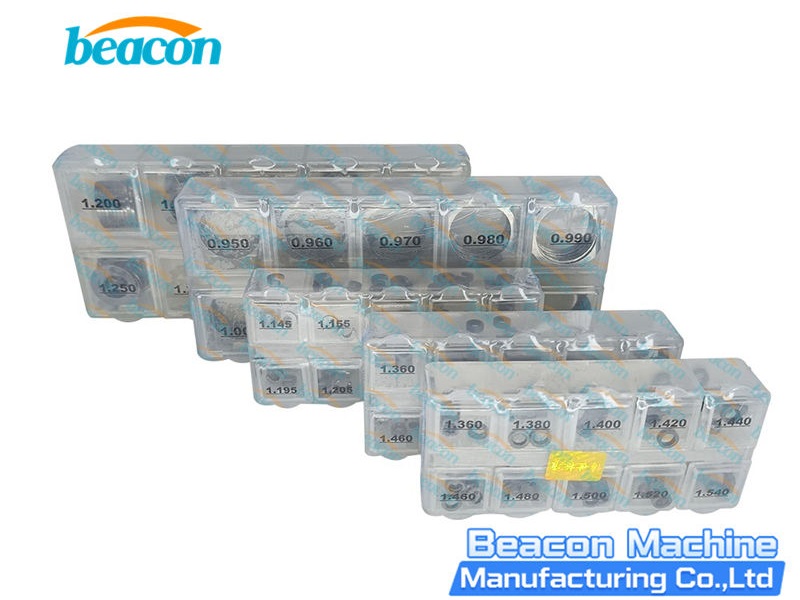
During common rail injector repair, replacing a calibration shim may change internal travel, spring preload and injection response at the same time. Before selecting a shim, identify its position, the part it acts on and the measurement associated with it.
This article mainly covers solenoid-controlled common rail injectors for which a repair procedure exists. Public Bosch CRI/CRIN information provides the principal structural reference. Piezo injectors and other designs require their own repair procedures. The relationships between parameters are explained here without giving universal shim thicknesses, tolerances or adjustment amounts across injector models.
1. Identify what each shim adjusts
Bosch's official Stage-3 shim brochure lists separate adjustment components for armature stroke, residual air gap, nozzle needle stroke and spring force, with the applicable injector series identified. Parts that look similar may serve entirely different purposes. Source: Bosch CRI/CRIN Stage-3 shim brochure
| Adjustment position or item | Directly adjusted feature | What to check |
|---|---|---|
| Armature-stroke adjustment component | Geometric travel of the armature and related control-valve mechanism | Specified mechanical and electrically actuated measurements, and assembly condition |
| Residual-air-gap adjustment component | Gap left between the armature and magnetic core when the armature reaches its specified attracted position | Measurement datum, component design and applicable injector model |
| Needle-stroke adjustment component | Permitted travel of the nozzle needle; some designs use a shim or thrust member | Distinguish it from the needle-spring adjustment component |
| Spring-force adjustment shim | Installed preload condition of the valve spring or nozzle spring | Whether the spring itself is serviceable, and the specified force or dimension |
This table identifies functions. It cannot establish whether a particular shim should be thicker or thinner. The direction of an adjustment must be determined from the specific design and repair data.
2. What does AHE indicate?
AHE, also written AHe, comes from the German Ankerhub elektrisch and generally refers to armature stroke measured under electrical actuation. A study of Bosch CRI1 injectors distinguishes mechanically measured AH from electrically measured AHe; in the design studied, the measurement relates to travel of the control-valve ball. Source: study of common rail injector testing, terminology and measurement description
Three distinctions matter when interpreting AHE:
- Armature or control-valve travel and nozzle needle stroke are different measurements.
- Stroke is a travel distance; response time is the time needed for an action. One cannot substitute for the other.
- An electrically actuated measurement must be interpreted under the conditions specified by its procedure. It does not directly represent actual movement at every rail pressure.
An armature-stroke adjustment component sets the travel range of the relevant mechanism by changing the dimensional relationship in the assembly. A Bosch patent on armature-stroke adjustment describes selecting a shim using actual measured component dimensions and a target stroke, while accounting for the specified loading and clamping conditions. Source: Bosch armature-stroke adjustment patent EP1744054B1
When a measured value misses its target, first check the fixture, measurement zero, loading method and assembly condition. Then select the adjustment component using the applicable procedure. Without model-specific data, no general formula such as “change shim thickness by the measured error” is reliable.
3. The air gap affects armature operating conditions
The measurement state must be specified when discussing the air gap. The gap with the armature in its closed position must not be confused with the residual air gap remaining when it reaches its specified attracted end position. Bosch uses RLS for the residual air gap, defined by the relative positions of the armature and magnetic core at the specified position. Source: Bosch magnetic-assembly patent EP3317890B1
Components associated with the residual air gap can also affect repeatability. Another Bosch patent describes a particular floating air-gap disc that can develop hydraulic adhesion, potentially changing armature closing times and injection quantity. This makes shim thickness, contact condition and positioning relevant inspection points. Source: Bosch magnetic-assembly patent EP3014109B1
These patents explain structural mechanisms; they do not provide repair limits for every injector model. In repair work, restore the specified air gap and retest the affected strokes and injection performance.
4. Check needle stroke and spring preload separately
Needle stroke describes how far the nozzle needle moves away from its seat. In a design with a stroke-limit adjustment component, changing the relevant component dimension can alter the maximum permitted travel. A nozzle-spring shim adjusts the installed preload of the spring. Bosch's component diagrams and parts information label these functions separately. Source: Bosch CRI2 injector diagram
Maximum permitted stroke must also be distinguished from the stroke actually reached in an individual injection. With a short energizing time, the needle may begin closing before it reaches its maximum stroke. An experimental study of a solenoid diesel injector observed nonlinear injection behavior in the short-pulse region and related it to the needle not attaining full lift. Source: study of hydraulic interactions during multiple injections with a solenoid injector
Accordingly, a compliant maximum stroke alone does not establish that pilot, idle and main injection all meet specification. Increasing the maximum permitted stroke also does not guarantee a larger injection quantity at every test point.
5. Why “a thicker shim means more fuel” is unreliable
The quantity delivered in one injection depends on how flow changes throughout that event. A calibration shim may affect opening, closing or travel range. Rail pressure, drive conditions and internal hydraulics also contribute to the result.
An experimental study of Denso solenoid common rail injectors analyzed the relationship between calibration shims and idle injection quantity, using a nonlinear model to describe the test results. Such work supports analyzing adjustment effects for the particular design and test conditions; a trend observed for one model cannot simply be applied to another. Source: experimental-design study of injection quantity adjustment
Avoid these assumptions during repair:
- Low delivery at one test point automatically means insufficient needle stroke.
- Passing main injection means pilot and idle injection also pass.
- Passing AHE makes return flow, sealing and injection-quantity tests unnecessary.
- Improvement at one test point after changing a shim means the repair is complete.
Wear, valve-seat damage and abnormal springs need separate attention. Bosch remanufacturing information notes that valve assemblies and spring condition affect injection action and return-flow behavior. Changing a shim does not replace inspection and repair of these faults. Source: Bosch eXchange common rail systems brochure
6. How should measurement and retesting be organized?
The following work sequence is compiled from the structural information and test studies above. The procedure for the exact injector model still governs the work.
1. Confirm the model and repair scope
Record the complete part number. Confirm which items may be repaired, which parts are applicable, and which measurement methods and test programs are required. Similar appearance or a shared brand cannot substitute for this information.
2. Preserve a pre-adjustment baseline
Under the specified conditions, record injection quantity, return flow and the relevant electrical and sealing test results. During disassembly, record each adjustment component's location and actual dimension, together with the related stroke measurements. Handle visibly damaged components according to the repair procedure first.
3. Measure and select shims by the specified method
Use a suitable fixture, measuring instruments and the prescribed drive and loading conditions. Clean the contact surfaces and confirm the zero point before measuring. Do not assume the marked package size equals the actual dimension of a used shim, or equate an instrument's display resolution with measurement accuracy.
4. Recheck related parameters after adjustment
Complete adjustment and tightening in the manufacturer's order, recording every change. After replacing an armature-stroke or air-gap component, recheck the dimensions affected by that change as the procedure requires. Check more than the single parameter just adjusted.
5. Complete the specified bench tests
Repeat the injection, return-flow, sealing and other tests required for that part number, covering the specified rail pressures and drive durations. If results vary, investigate the cause and confirm repeatability rather than retaining a single passing reading.
Conclusion
Calibration shims connect assembly dimensions with injection performance. Reliable repair requires three things: identify what each adjustment component does, restore the dimensions and forces required for that model, and verify injection performance on the test bench.
Interpret AHE, residual air gap, needle stroke and injection quantity together. Dimensional measurements guide the adjustment; tests across operating conditions verify the repair outcome.
Related products
Beacon Machine Manufacturing Co.,ltd
Quick Links
contact
WhatsApp: +86-13570429157
Tel / Wechat: 0086-13570429157
Email: ellenzhang@beacon-machine.com
Add: High Technology Industrial Park of Taian city,Shandong province,China


quick order
We will reply to your email within 2 hours