
Beacon Machine Manufacturing Co.,ltd
 Language
  EN
EN RU
RU ES
ES DE
DE EL
EL IT
IT JA
JA KO
KO PT
PT ID
ID SR
SR UK
UK VI
VI TH
TH TR
TR MS
MS BE
BE AR
ARCommon Rail Pump Test Results Explained: Delivery, Pressure Stability, Return Flow and Efficiency
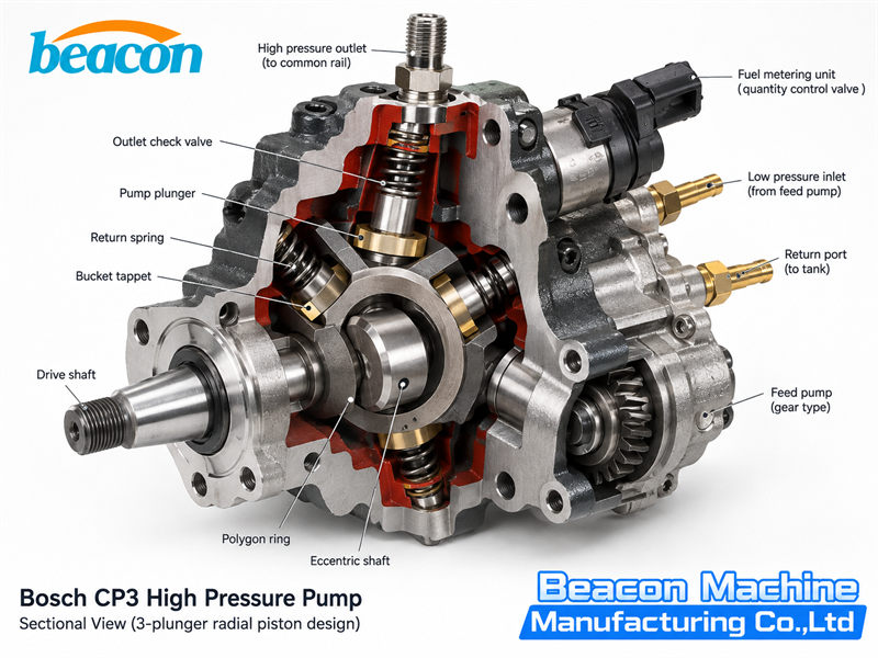
A common rail pump that builds pressure still needs further checks: how much fuel it delivers at the specified speed, whether pressure remains stable, whether return flow meets the specification, and whether the results remain consistent in repeated tests.
Together, these measurements determine the practical value of a test report. Looking only at maximum pressure can overlook insufficient delivery at high pressure, metering-control faults or performance that deteriorates as temperature changes.
This is the companion article to Common Rail Injector Test Results Explained: Injection Quantity, Return Flow, Response Time and BIP. It explains four categories of data from off-vehicle common rail pump tests and how technicians can use them together to decide what to check next.
1. Confirm the Test Conditions Before Reading the Results
The common rail pump pressurizes fuel and supplies the rail; the injectors then control injection quantity and timing. DENSO describes this division of functions and the differences in construction and delivery capacity between pump families. Each result must therefore be matched to the complete pump part number and its specific test plan. Source: DENSO common rail pump operation
Check the following information first:
- Pump identification: manufacturer, complete part number, metering-valve type and test-plan version.
- Drive conditions: direction of rotation, actual pump-shaft speed and the definition of speed used by the software.
- Low-pressure supply: inlet pressure or supply conditions, connections and bleeding status.
- Test-fluid conditions: specified calibration fluid, measurement temperature and stabilization time.
- Control conditions: target rail pressure, metering-valve drive method and test-bench pressure-control method.
- Measurement conditions: flow units, acquisition time, return-flow measurement location and specified backpressure.
For example, L/h, mL/min and delivery volume per revolution express data in different forms. Before comparing two reports, convert the units and confirm that speed, pressure and control conditions match.
Hartridge lists automatic pressure control and repeatable test plans among the basic features of its common rail pump equipment. These conditions determine whether tests from different batches can be compared meaningfully. Source: Delphi/Hartridge CRp-PC information
2. Delivery: How Much Fuel Does the Pump Supply at the Specified Pressure?
Delivery usually refers to the quantity supplied from the high-pressure outlet under a specified operating condition. The measurement location, units and metering method are defined by the test-bench instructions and test plan.
Read delivery, actual pressure, pump-shaft speed and metering-valve control conditions together.
What Should Be Checked When Delivery Is Low?
Work through the following checks:
- Confirm that inlet supply meets the requirements and that the filter and supply lines are unrestricted.
- Check that the pump and pipes have been fully bled.
- Confirm that actual speed reaches the specified test value.
- Verify the metering-valve type, wiring and drive parameters.
- Check for abnormal leakage in the high-pressure connections and pressure-control circuit.
- Once these conditions are correct, inspect the pump plungers, valves and sealing areas.
These checks provide diagnostic directions. A single delivery value cannot locate a particular damaged part. Delphi also uses further testing to distinguish an internal mechanical pump problem from an inlet metering valve fault. Source: Delphi common rail diagnostic case
Why Can a Pump Reach High Pressure and Still Fail the Delivery Test?
Pressure and flow describe different operating capabilities. A pump may reach the target pressure when flow demand is low, while its output remains below specification at a test point requiring more fuel.
Complete every speed, pressure and metering-control point required by the test plan. Passing a low-pressure point cannot replace a high-pressure delivery test, and passing one point does not establish that the entire performance curve meets the specification.
Is Higher Delivery Better?
Delivery should remain within the range specified for the test point. At metering-controlled points, an excessive reading calls for checks of the selected plan, valve compatibility, drive signal and metering-control condition.
DENSO explains that the SCV controls pressure by regulating the quantity of fuel pumped. Normally open and normally closed versions have opposite de-energized states, so the drive settings must match the exact valve. Source: DENSO SCV operation and types
3. Pressure Stability: Can the Pump Maintain the Target Pressure?
Pressure stability requires observation over time. Review the report or live trace for:
- The difference between actual and target pressure;
- the variation during the stabilized period;
- the pressure rise or fall after changing test points;
- the time required to stabilize;
- changes when the same operating point is repeated.
Some equipment displays an averaged or filtered pressure value. The meaning of a stable screen reading depends on the sampling and display method. Analyzing rapid pressure fluctuations requires suitable measurement capability.
Where Can Pressure Fluctuations Come From?
The checks include inlet supply, air, actual speed, the metering valve, pressure-control valve, pressure sensor and the pump itself.
The test bench also participates in pressure regulation. Hartridge states that stabilization is affected by the condition of the pump and the size of the pressure change, and that pressure needs continuous adjustment as the pump warms up. Source: Hartridge HB401 automatic pressure control
On that basis, investigate fluctuations in this order:
- Confirm inlet supply, bleeding and fluid temperature.
- Check speed and the drive connection.
- Verify metering-valve and pressure-control settings.
- Check the sensor, wiring and test-bench control condition.
- Combine delivery and return-flow results before judging an internal pump fault.
Benches may differ in piping, rail volume, control strategy and data processing. Before comparing fluctuation values across equipment, confirm that the measurement methods are equivalent.
4. Return Flow: Identify Which Flow Has Been Measured
Interpret pump return flow from the internal fuel circuit and the test-bench connections.
Bosch explains that the CP4 metering unit controls fuel supply according to demand, while surplus fuel returns to the tank through a low-pressure connection. Pump return can therefore include flow permitted by the design. Source: Bosch CP4 high-pressure pump operation
Before measuring, distinguish between:
- Flow from the return port of the pump under test;
- flow discharged by the rail or test-bench pressure-control valve;
- total return after several circuits have joined.
Once these circuits have merged, the total measured flow cannot directly represent the pump's internal leakage.
How Should Excessive Return Flow Be Interpreted?
First confirm the pump number, connections, inlet conditions, fluid temperature, speed and control parameters. Return exceeding the specified range under those conditions provides a basis for further diagnosis.
If high-pressure delivery also falls, internal leakage is one area to investigate. If high-pressure output remains normal, check which circuits are included in the measurement, the control-valve operating state and the specified range for that test point.
What Does Low Return Flow Indicate?
Check for restrictions in the return pipe, the correct adapter, the correct measurement channel and adequate inlet supply. Then inspect the internal circuit according to the pump type.
The objective is return flow that meets the specified test-point requirements. Pursuing a low reading alone can conceal a connection, measurement or fuel-circuit problem.
5. Efficiency: What Does the Percentage on the Report Mean?
Efficiency needs a definition. A delivery-to-reference ratio, volumetric efficiency and overall efficiency can all be expressed as percentages, but they use different calculations.
1. Delivery Relative to a Reference Value
If the software uses this calculation:
Measured delivery ÷ reference delivery × 100%
the value describes the relationship between the measurement and the reference. It can help compare performance deviations, but it does not directly show how much mechanical energy the pump converts into hydraulic energy.
Check the software documentation to establish whether the reference is a nominal value, a lower limit or another baseline.
2. Volumetric Efficiency
In general hydraulic-pump theory, volumetric efficiency is defined as:
Volumetric efficiency = actual output flow ÷ theoretical output flow × 100%
Parker gives this formula in its technical literature. The calculation requires the theoretical displacement, speed and applicable conditions to be defined. Source: Parker hydraulic formulas
Common rail pumps are also affected by inlet metering or other delivery-control methods. At partial-delivery points, the control system deliberately reduces fuel entering the high-pressure pumping section. Dividing actual flow by the theoretical flow at maximum geometric displacement cannot, by itself, establish wear or repair acceptance.
3. Overall Efficiency
Overall efficiency describes the relationship between output and input power:
Overall efficiency = hydraulic output power ÷ pump-shaft input power × 100%
Pump-shaft input power requires reliable torque and speed measurements, or another validated power-measurement method. The test-bench motor's rated power cannot substitute for the actual power entering the pump at the test point. Total bench electrical consumption also includes losses in the motor, transmission, cooling and auxiliary systems. Source: Parker efficiency and power formulas
Using the usual hydraulic approximation:
Hydraulic power (kW) ≈ pressure difference (bar) × flow (L/min) ÷ 600
This formula helps explain the relationship between pressure, flow and power. Accurate common rail pump efficiency evaluation also requires the prescribed treatment of measurement locations, fuel compressibility and corrections. In particular, verify whether flow has been converted to a common reference state. Source: Parker hydraulic power formula
If the report does not define its efficiency calculation or provide the corresponding input-power or theoretical-flow data, use a directly verifiable repair statement, such as “All delivery test points are within the specified limits.”
6. Read the Results Together
The table below helps organize further checks. Confirm the actual fault using the test and repair procedure for the specific pump.
| Result Pattern | Priority Checks |
|---|---|
| Target pressure reached, delivery below specification | Actual speed, inlet supply, metering-valve control, flow measurement and internal leakage |
| Both pressure and delivery low | Inlet supply, air, drive conditions, metering control, high-pressure leakage and the pump itself |
| Pressure fluctuates continuously and delivery is unstable | Bleeding, supply stability, speed, control valves, sensor and test-bench regulation |
| Delivery falls while the pump's own return exceeds its limit | Confirm the return measurement location, then check internal leakage and related valves |
| Normal delivery with excessive total return | Separate pump return from pressure-control discharge; verify connections and specifications |
| Passes cold, but readings move outside limits after temperature stabilization | Calibration fluid, temperature control, measurement corrections and temperature-related internal leakage or valve behavior |
| Large differences in repeated tests at the same point | Air, temperature, connections, drive, metering system and intermittent sticking |
| Pump passes off-vehicle testing but vehicle rail pressure remains low | Vehicle low-pressure supply, injector return, rail-pressure control devices, sensor and wiring |
The last pattern requires the bench result to be considered alongside vehicle diagnosis. Delphi recommends checking leakage through the rail, high-pressure valve and injectors after the pump passes an isolated test. Source: Delphi fuel-system starting diagnosis
7. What Should a Useful Repair and Verification Report Record?
At minimum, record the complete pump number, test-plan version, date, calibration fluid and temperature, inlet conditions, pump-shaft speed, target and actual pressure, metering-valve control conditions, delivery, return measurement location, permitted ranges and final verdict.
Retain repeat-test data for borderline or unstable readings. Use the same plan and conditions before and after repair so that performance changes can be assessed.
Workshops carrying out off-vehicle common rail pump tests can consider the Beacon CR910 Common Rail Injector and Pump Test Bench. Its product information lists common rail pump testing, test-speed and rail-pressure control, flow recording and reporting. Confirm coverage, adapters and test data for each pump part number.
When completing a report, state which operating points passed, which measurements exceeded limits and what the repeat tests showed. “Pressure normal” does not cover delivery, return flow and control stability. Recording these conditions makes the result useful for repair, verification and handover.
Related products
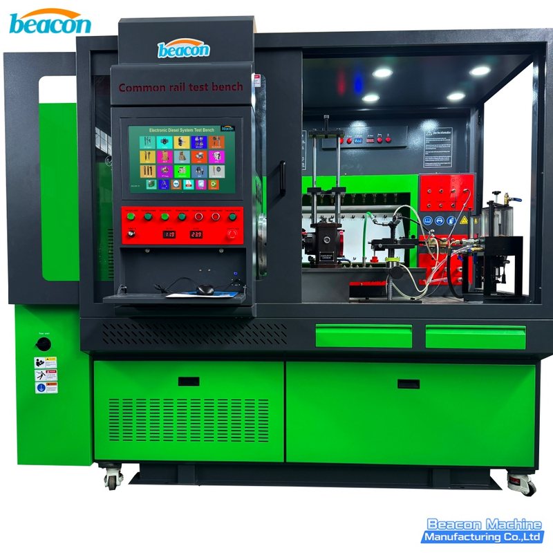
CR919PLUS Common Rail Injector and Pump Test Bench
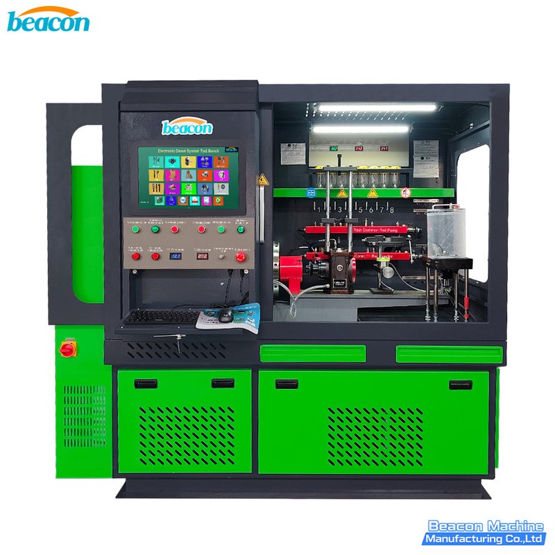
CR910 Common Rail Injector and Pump Test Bench

CR918-PRO Full Function Common Rail HEUI EUI EUP Test Bench with 4 Tanks
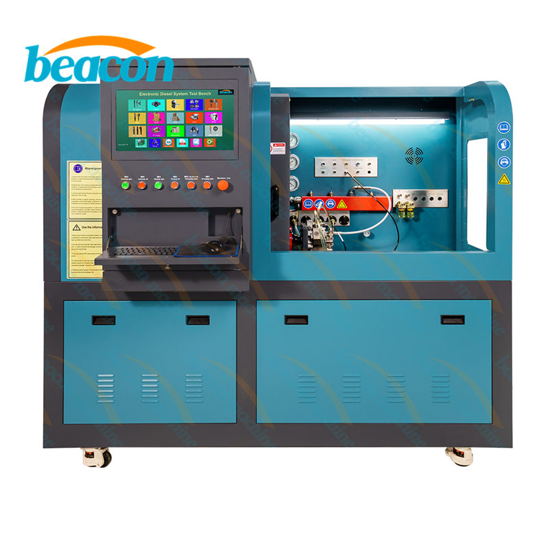
Beacon CR819S All-Function Common Rail Injector, Pump, EUI/EUP & HEUI Test Bench
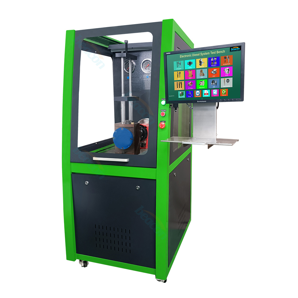
CR1017-CRI CRP EUI HEUI Multifunction Common Rail Pump Injector Test Bench
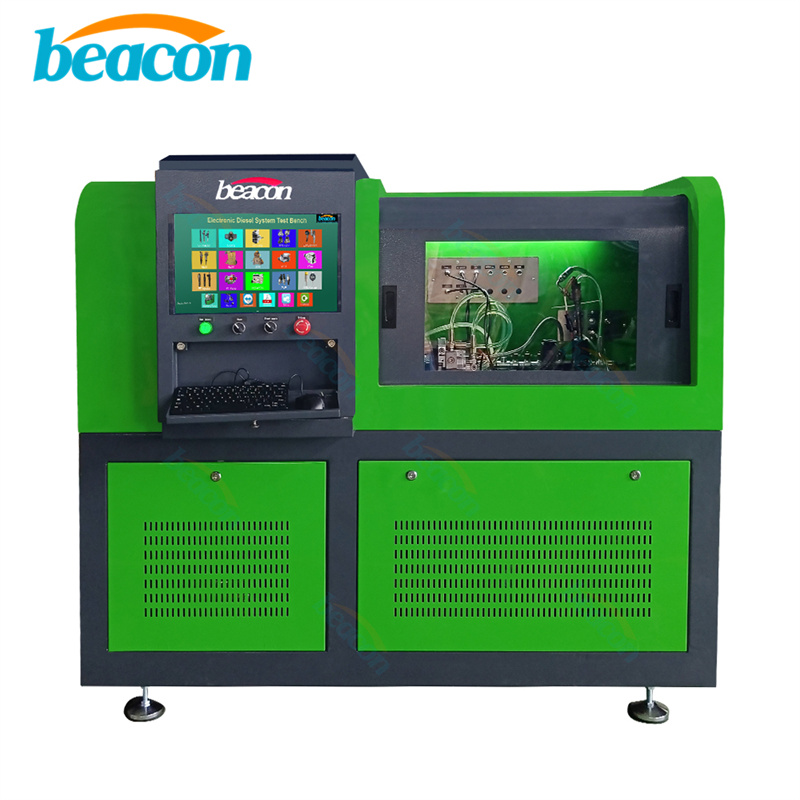
CR819 Common Rail Injector Pump Test Bench
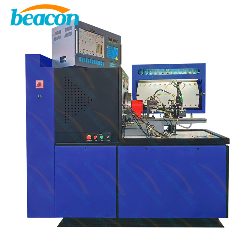
CRS900S Diesel Injection Pump Test Bench - Mechanical & Common Rail System
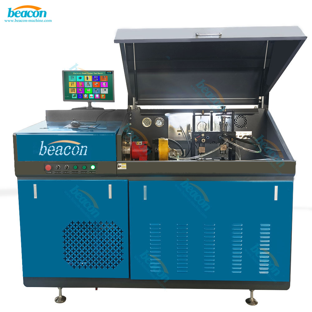
CR708 Common Rail & Piezo Injector Pump Test Bench
Beacon Machine Manufacturing Co.,ltd
Quick Links
contact
WhatsApp: +86-13570429157
Tel / Wechat: 0086-13570429157
Email: ellenzhang@beacon-machine.com
Add: High Technology Industrial Park of Taian city,Shandong province,China


quick order
We will reply to your email within 2 hours