
Beacon Machine Manufacturing Co.,ltd
 Language
  EN
EN RU
RU ES
ES DE
DE EL
EL IT
IT JA
JA KO
KO PT
PT ID
ID SR
SR UK
UK VI
VI TH
TH TR
TR MS
MS BE
BE AR
ARCommon Rail Injector Test Results Explained: Injection Quantity, Return Flow, Response Time and BIP

A common rail injector test report is only useful when the technician understands what each value means and how the values interact. Injection quantity, return flow, response time, and the BIP signal describe different parts of the same event: the injector receives an electrical command, its control valve and needle move, fuel is delivered to the cylinder, and a controlled amount of fuel returns through the leak-off circuit.
No single number should be used to condemn an injector. Always compare the measured values with the correct test plan for the injector part number, rail pressure, energizing time, test-oil temperature, and operating point. A stable test bench and clean calibration fluid are prerequisites for a reliable diagnosis.
This article explains injector-side test data; the companion guide to common rail pump test results covers delivery, pressure stability, return flow and efficiency on the fuel-supply side.
1. Injection Quantity: How Much Fuel Is Actually Delivered?
Injection quantity is the measured amount of calibration fluid delivered by the nozzle during a defined number of injection cycles. A professional test plan normally checks several operating points, such as full-load delivery, medium-load delivery, idle delivery, and one or more pilot-injection conditions. The names of these points vary by injector manufacturer and database.
- Quantity below the reference range may be associated with nozzle restriction, a sticking needle, insufficient needle lift, incorrect armature settings, weak actuation, or failure to reach the commanded rail pressure.
- Quantity above the reference range can result from nozzle-seat wear, excessive needle movement, incorrect internal adjustment, or a control valve that remains open too long.
- Unstable or poorly repeatable quantity often points to contamination, trapped air, temperature variation, pressure instability, or intermittent mechanical movement.
The pattern across operating points matters more than one isolated result. An injector may pass at high load but fail pilot injection because small deliveries demand much faster and more precise control.
2. Return Flow: A Window into Internal Leakage and Control
Return flow, also called back leakage or leak-off, is the fuel leaving the injector through its return circuit during the test. Some return flow is necessary because it supports hydraulic control and lubrication. The correct result is therefore not “zero return,” but a stable value within the specified range.
- Excessive return flow commonly indicates leakage across the control valve, valve seat, guide clearances, or other worn internal sealing surfaces. The injector may then struggle to build the hydraulic force needed to lift the needle correctly.
- Abnormally low return flow may indicate a restricted return passage, incorrect assembly, insufficient control-valve movement, or a test connection problem.
- Return flow that changes sharply between repeated tests suggests contamination, air in the circuit, temperature instability, or an intermittently sticking component.
Return flow must be interpreted together with injection quantity. High return combined with low delivery strongly supports an internal-leakage diagnosis, while low delivery with normal return may direct attention toward the nozzle, mechanical adjustment, actuation, or test conditions.
3. Response Time: How Quickly Does the Injector React?
Response time describes the delay between the electrical command and the injector's hydraulic or mechanical response. Depending on the test system, the displayed value may be derived from current, voltage, pressure, flow, or needle-motion signals. For that reason, technicians should compare response-time values only under the same test method and database specification.
A slow or inconsistent response may be caused by an incorrect armature air gap, excessive dynamic stroke, a weak or damaged solenoid coil, control-valve wear, a sticking needle, trapped air, contamination, or an unsuitable electrical drive signal. Piezo injectors use a different actuator principle, so their response data must not be evaluated against solenoid-injector limits.
4. BIP Signal: Seeing the Beginning of Injector Movement
BIP is commonly described as the Beginning of Injection Period. On compatible solenoid injectors and test equipment, a change in the electrical waveform can be used to identify the point at which the magnetic and hydraulic system begins its effective movement. This gives the technician a timing reference that a simple flow measurement cannot provide.
A missing, delayed, or unstable BIP signal does not automatically identify one failed component. It tells the technician to investigate the complete actuation chain: coil condition, connector contact, armature lift and air gap, control-valve movement, rail pressure, wiring, and the test bench's drive and measurement setup. For a deeper explanation, see Beacon's guide to the BIP signal in common rail systems.
How to Read the Four Results Together
| Observed Pattern | Likely Diagnostic Direction | Next Checks |
|---|---|---|
| Low injection quantity + high return flow | Internal hydraulic leakage | Control valve, valve seat, sealing surfaces, internal clearances |
| Low quantity + normal return + slow response | Actuation or mechanical-adjustment problem | Coil, armature air gap, dynamic stroke, needle movement |
| High quantity + normal return | Nozzle or internal adjustment outside specification | Nozzle seat, needle lift, control-valve travel, calibration settings |
| Normal main delivery + failed pilot delivery | Poor control of very small injections | Response stability, armature settings, control valve, contamination |
| Unstable quantity + unstable return + irregular BIP | Test-condition issue or intermittent injector movement | Air removal, oil temperature, rail-pressure stability, connections, cleanliness |
| Repeatable flow values + missing BIP | Signal compatibility or electrical measurement issue | Injector type, test-plan support, BIP cable, sensor and drive settings |
A Reliable Diagnostic Workflow
- Identify the exact injector. Confirm the manufacturer, part number, actuator type, and correct database plan.
- Stabilize the test conditions. Use clean calibration fluid, remove air, control temperature, and verify rail-pressure stability.
- Run the complete test plan. Do not judge the injector from one load point.
- Check repeatability. Repeat abnormal points before dismantling the injector.
- Interpret the values as a group. Compare delivery, return flow, response, and BIP instead of following one number.
- Inspect and adjust only with verified specifications. Record the original measurements before changing internal parameters.
- Retest after repair. The injector must pass every required operating point before coding or returning to service.
Why Test-Bench Capability Matters
A useful diagnosis requires more than producing pressure. The test system must control pressure and temperature, drive the injector correctly, measure small and large deliveries repeatably, monitor return flow, and support the injector's electrical characteristics. When BIP analysis, piezo testing, or injector coding is required, confirm that these functions are supported for the exact injector family.
The Beacon EPS210S common rail injector test bench combines solenoid and piezo injector testing with BIP analysis and coding functions, allowing workshops to evaluate flow results and actuation behavior within one controlled test process.
Final Takeaway
Injection quantity shows the delivered fuel, return flow reveals hydraulic leakage and control behavior, response time shows how quickly the injector reacts, and BIP adds an electrical timing reference. The strongest diagnosis comes from the relationship between all four results, verified under the correct test conditions and repeated after repair.
Related products
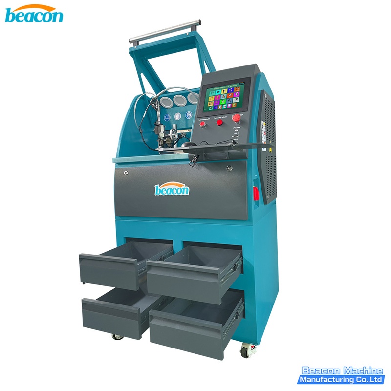
EPS206 PLUS Common Rail Injector Test Bench | Piezo & Coding
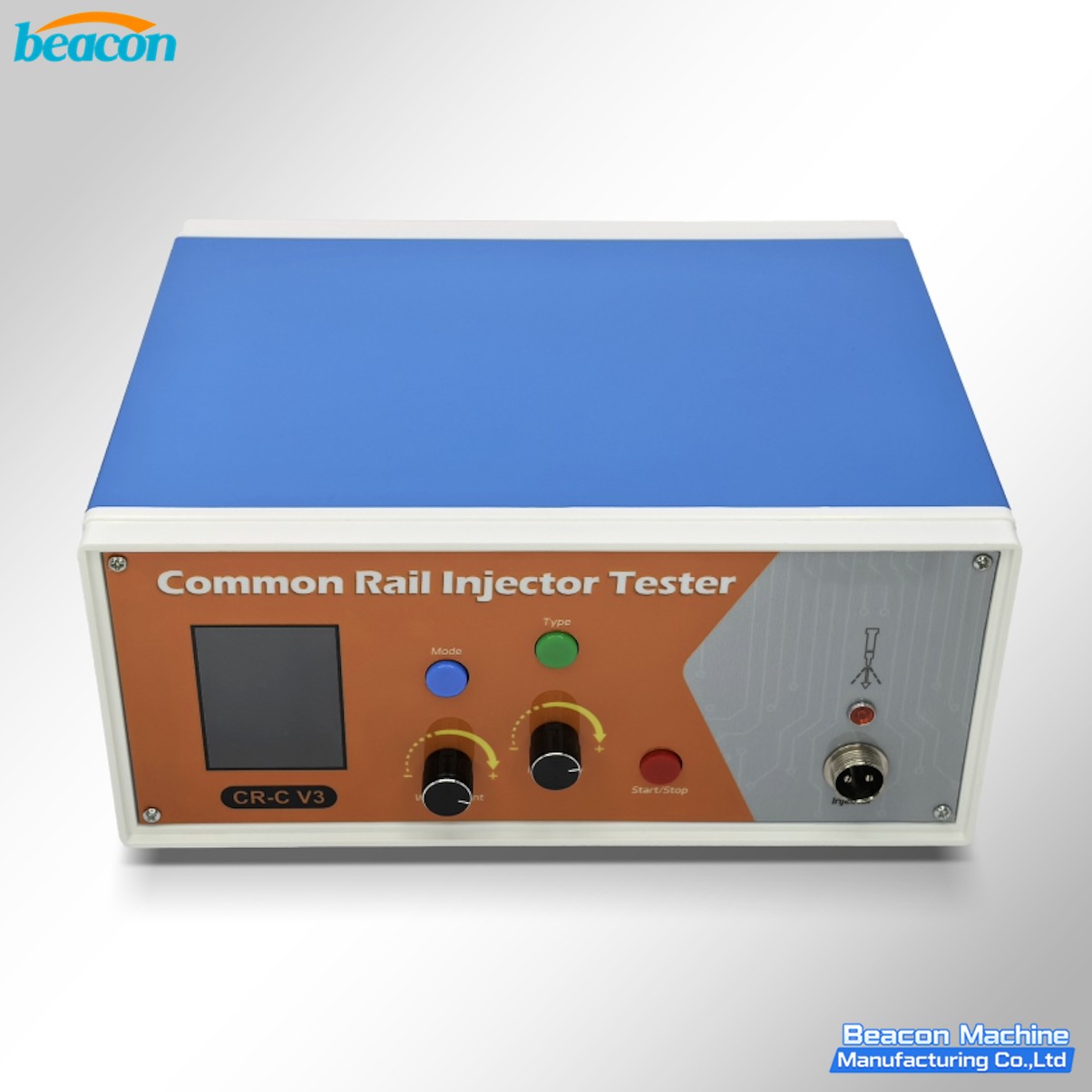
CR-C V3 Common Rail Injector Tester for Solenoid and Piezo Injectors
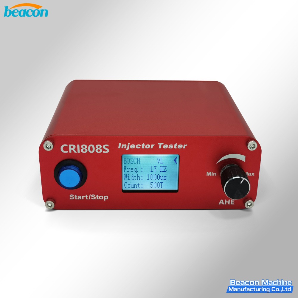
CRI808S Common Rail Injector Tester
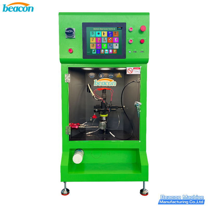
EPS290 Common Rail Injector Test Bench
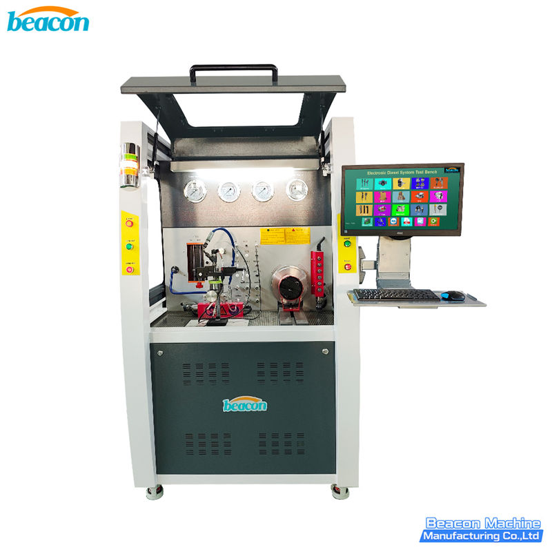
CR1029 High Pressure Common Rail Comprehensive Performance Test Bench - CR Injector & Pump Tester
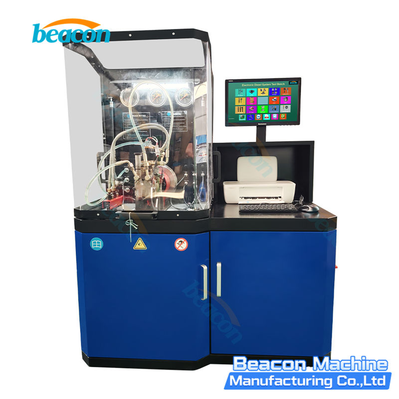
CR302 Common Rail Injector Test Bench
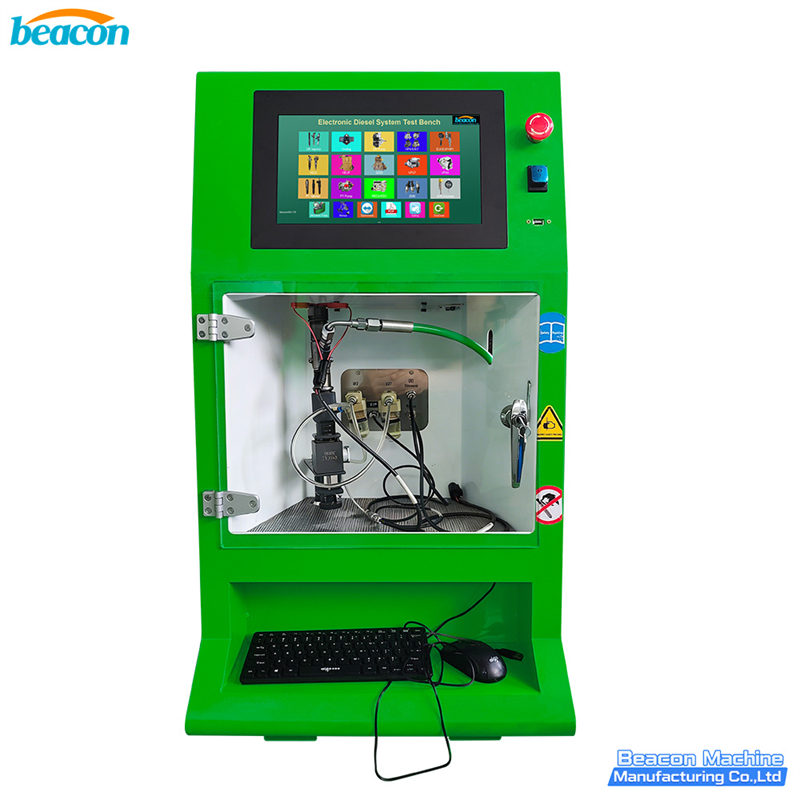
EPS212 Common Rail Injector Test Bench

CR918-PRO Full Function Common Rail HEUI EUI EUP Test Bench with 4 Tanks
Beacon Machine Manufacturing Co.,ltd
Quick Links
contact
WhatsApp: +86-13570429157
Tel / Wechat: 0086-13570429157
Email: ellenzhang@beacon-machine.com
Add: High Technology Industrial Park of Taian city,Shandong province,China


quick order
We will reply to your email within 2 hours