
Beacon Machine Manufacturing Co.,ltd
 Language
  EN
EN RU
RU ES
ES DE
DE EL
EL IT
IT JA
JA KO
KO PT
PT ID
ID SR
SR UK
UK VI
VI TH
TH TR
TR MS
MS BE
BE AR
ARHow to Test Piezo Diesel Injectors: Capacitance, Insulation, Leakage and Response
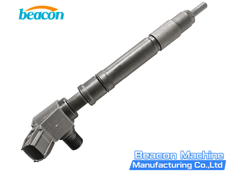
Piezo common rail injectors provide fast actuation, short injection intervals and flexible multiple-injection control. Bosch explains that a piezo actuator consists of many layers of piezoelectric ceramic. Applying voltage produces a very small displacement, which the injector mechanism uses to control needle movement.
The actuator, electrical connections and hydraulic control components all influence injection. An accurate diagnosis therefore combines capacitance, insulation, leakage, delivery, response time and repeatability instead of relying on one value. Bosch technical description of piezo common rail injectors
Important: There is no universal pass/fail value for piezo-injector capacitance, insulation resistance, test voltage, return flow or response time. Always use the current test plan for the complete injector part number.
Why Piezo Injectors Require a Different Test Method
A solenoid injector uses a coil to generate magnetic force, so resistance and inductance are common electrical checks. A piezo injector uses a piezo stack as its main actuator and behaves as a capacitive electrical load. Capacitance and insulation condition are therefore important preliminary checks.
Use equipment that explicitly supports piezo injectors, the correct test cable and the correct test plan. Delphi states that one of its electronic test kits for common rail solenoid injectors is not compatible with direct- or indirect-acting piezoelectric injectors. A tool described as a common rail injector tester may therefore have limited technology coverage. Delphi electronic injector test-tool instructions
1. Capacitance Test: Checking the Electrical Condition of the Piezo Actuator
What Does the Capacitance Test Check?
A capacitance test checks the overall electrical condition of the piezo stack and its internal connection circuit. Delphi and Hartridge list capacitance as a dedicated measurement for piezo injectors, confirming its role as a basic electrical diagnostic parameter. Hartridge Sabre CRi Expert specifications
- Select the test plan from the complete injector part number.
- Use a piezo-capable tester or the capacitance function specified by the equipment manufacturer.
- Keep the connector, test cable and terminals clean and dry.
- Avoid touching the test terminals because contamination, contact resistance and body capacitance can affect the reading.
- Allow the temperature to stabilize and record the test conditions.
- Compare the result with the reference data for that exact injector.
What Can an Abnormal Capacitance Reading Indicate?
A capacitance reading that is clearly outside the specified range may be associated with one or more of the following conditions:
- Internal damage to the piezo stack;
- an open circuit or poor internal connection;
- a partial short between piezo layers;
- a fault in the connector, adapter cable or measurement circuit;
- selection of the wrong injector type or test plan.
Capacitance evaluates only part of the electrical system. An injector can pass capacitance and still have an insulation fault, control-valve wear, poor nozzle sealing, abnormal return flow or incorrect delivery.
Why Is There No Universal Capacitance Specification?
Nominal capacitance and tolerance can differ between manufacturers, actuator designs and injector part numbers.
Hartridge publishes a 0–12 µF capacitance measurement range for one test bench. This figure is an equipment measurement range, not the acceptable range for every piezo injector. The actual decision limit must come from the test plan assigned to the complete part number.
2. Insulation Test: Checking Electrical Leakage Between the Terminals and Injector Body
Purpose of the Insulation Test
The insulation test checks the integrity between the electrical terminals and the metal injector body. Deteriorated insulation can cause drive faults, control-unit protection, intermittent operation or failure to inject.
Possible influences on insulation condition include:
- Water inside the connector;
- fuel, cleaning fluid or other contamination on the terminals;
- connector damage;
- aged or broken-down internal insulation;
- damage to the piezo actuator or internal wiring.
Bosch lists capacitance, insulation and piezo-injector integration tests as separate functions of the FSA 050. Capacitance and insulation therefore evaluate different electrical failure modes and must be checked separately. Bosch FSA 050 technical information
Safety Requirements for Insulation Testing
Do not choose an insulation-test voltage arbitrarily. An unsuitable or excessive test voltage may damage the piezo stack, connector or internal electronics.
- Disconnect the injector from the vehicle control unit.
- Complete the approved discharge procedure specified by the test equipment.
- Use the dedicated adapter cable for the piezo injector.
- Select the test voltage specified by the injector manufacturer or test plan.
- Perform the prescribed insulation test between the terminals and injector body.
- Discharge the injector again after the test as directed by the equipment manufacturer.
A piezo element can store electrical charge. Follow the equipment safety procedure during removal, connection and measurement. Do not use an undocumented high-voltage test method or disconnect the injector while it is being driven.
3. Leakage Test: Separating Nozzle Leakage, Internal Leakage and Return Flow
“Leakage” can describe several different conditions. Record external leakage, nozzle sealing and return flow separately.
1. External Leakage
Inspect the following areas:
- High-pressure inlet and connection;
- injector body;
- return connection;
- test adapter and seals.
If an external leak is found, stop the high-pressure test before inspecting the connection, seal, installation and component condition.
2. Nozzle-Sealing Leakage
At the pressure and non-energized condition specified by the test plan, observe whether fuel drips or continuously seeps from the nozzle holes. Abnormal leakage may be related to the needle, needle seat, internal nozzle contamination or mechanical damage.
Holding pressure, observation time and permitted leakage must come from the test plan for that injector.
3. Return Flow or Internal Leakage
Bosch explains that return flow is produced during piezo-injector operation and travels back to the tank through the return line. Return flow is therefore a normal part of injector operation. Bosch piezo-injector operating principle
Return flow above the permitted limit at a specified test point may indicate:
- Leakage at an internal control valve or sealing surface;
- increased clearance in a guiding area;
- wear of internal components;
- particle contamination affecting sealing;
- an assembly or calibration problem.
Very low or near-zero return flow must also be interpreted from the injector design and test plan. Some injectors use special low-backleak or zero-backleak designs. A restricted return path, incorrect adapter or incorrect test condition can also produce an abnormally low result.
4. Response-Time Test: Observing the Delay from the Electrical Command to Injection
Response time describes the time required for the injector to produce the specified injection action after receiving a drive command.
Hartridge defines Full Event Response Time as the complete interval from electrical activation to the actual injection event. Other benches may use different signals, trigger points and calculations. Compare response time only on the same equipment, with the same test plan and under the same conditions. Hartridge response-time description
An abnormal response time may be associated with:
- Abnormal charging or discharging of the piezo actuator;
- poor contact in the drive cable or connector;
- slow control-valve movement;
- a sticking needle or other internal moving component;
- contamination affecting hydraulic control;
- unstable calibration-fluid temperature or viscosity;
- air in the injector or high-pressure circuit;
- incorrect pressure or drive settings.
Evaluate response time together with delivery, return flow and repeatability. One response-time reading cannot identify the specific damaged component.
Recommended Piezo-Injector Test Procedure
Step 1: Identify the Injector
Record the complete part number, manufacturer, injector technology and application. Select the exact test plan and adapters assigned to that part number.
Incorrect identification changes the drive parameters, test pressures, delivery references, return-flow limits and response-time limits.
Step 2: Inspect the Injector and Connections
Inspect the body, nozzle, threads, high-pressure inlet, return connection and electrical connector. Address cracks, severe corrosion, burned terminals or obvious mechanical damage before testing continues.
Step 3: Perform the Electrical Precheck
Complete the specified discharge procedure and then check:
- Capacitance;
- insulation between the terminals and body;
- condition of the connector and test cable.
Stop the drive test if the electrical precheck fails. Apply the manufacturer repair policy to decide whether the injector can be serviced further.
Step 4: Install the Injector and Stabilize the Test Conditions
Use the correct high-pressure connection, fixture and return adapter. Use the calibration fluid specified by the test bench. Bleed air from the circuit and stabilize pressure, fluid temperature and the measurement system.
Step 5: Perform Sealing and Leakage Tests
Follow the test plan to check:
- External high-pressure leakage;
- nozzle sealing in the non-energized condition;
- return flow at the specified pressures and operating points.
Step 6: Measure Delivery and Response Time
Complete the pilot, idle, main-injection and other operating points specified by the test plan. Record delivery, return flow, response time and stability at each point.
Workshops that need to test both piezo and solenoid common rail injectors off the vehicle can use the Beacon CR919 multifunctional diesel test bench. The product page confirms support for piezo and solenoid common rail injector testing. Acceptance limits must still come from the test plan for the complete injector part number.
Step 7: Repeat the Tests and Make a Combined Assessment
Repeat key operating points as required by the test plan. Poor repeatability may be related to air, temperature change, pressure fluctuation, connection faults, internal sticking or an unstable measuring system.
After repair, run the complete test procedure again. If the injector family requires a correction code, complete coding and vehicle ECU programming according to the applicable system procedure.
Common Result Patterns and Diagnostic Directions
| Test Result | Priority Diagnostic Direction |
|---|---|
| Capacitance outside the part-number specification | Part number and test plan, cable, terminal connection, piezo stack and internal connection |
| Capacitance passes but insulation fails | Moisture, terminal contamination, connector damage or deteriorated internal insulation |
| Electrical checks pass but return flow is too high | Control valve, sealing surfaces, internal guiding areas and assembly condition |
| Electrical checks pass but the nozzle drips | Needle, needle seat, nozzle contamination or mechanical damage |
| Low delivery with excessive return flow | Internal hydraulic leakage |
| Normal return flow with low delivery and slow response | Drive conditions, control valve, needle movement and internal contamination |
| Results vary significantly between repeated tests | Air, temperature, rail-pressure stability, connections, adapters or internal sticking |
These patterns organize further diagnosis. They do not replace the manufacturer disassembly standard or component-level repair data.
Frequently Asked Questions
Can a Standard Multimeter Fully Test a Piezo Injector?
A standard multimeter can perform only limited preliminary checks. A complete assessment normally requires piezo-capable equipment, the correct adapter and part-number-specific data.
Does Correct Capacitance Prove That the Injector Is Good?
No. The injector may still have an insulation fault, nozzle leakage, excessive internal return, incorrect delivery, slow response or poor repeatability.
Is Lower Return Flow Always Better?
Return flow must meet the specification for the injector at the specified test point. An unusually low result may come from the injector design, a restricted return path, the adapter or an incorrect test condition.
Can a Standard Megohmmeter Be Used for the Insulation Test?
Only use an instrument, test voltage and method approved by the injector manufacturer or dedicated test equipment procedure. An arbitrary test voltage can damage the injector.
Can an Abnormal Response Time Identify the Damaged Part?
Response time indicates the injector actuation condition but cannot locate a fault by itself. Combine it with capacitance, insulation, delivery, return flow and repeatability.
Conclusion
A reliable piezo-injector test follows a clear sequence: identify the injector, complete the electrical precheck, inspect sealing, measure return flow, test delivery, measure response time and verify repeatability.
Capacitance evaluates the piezo actuator and its connection circuit. Insulation testing identifies electrical leakage risk between the terminals and body. Leakage tests assess nozzle sealing and internal hydraulic condition. Response time shows the complete actuation process.
Interpret every result under the correct calibration-fluid, temperature, pressure, drive and part-number-specific test conditions. No single parameter represents the overall performance of a piezo injector.
Technical Sources
Related products

EPS206 PLUS Common Rail Injector Test Bench | Piezo & Coding
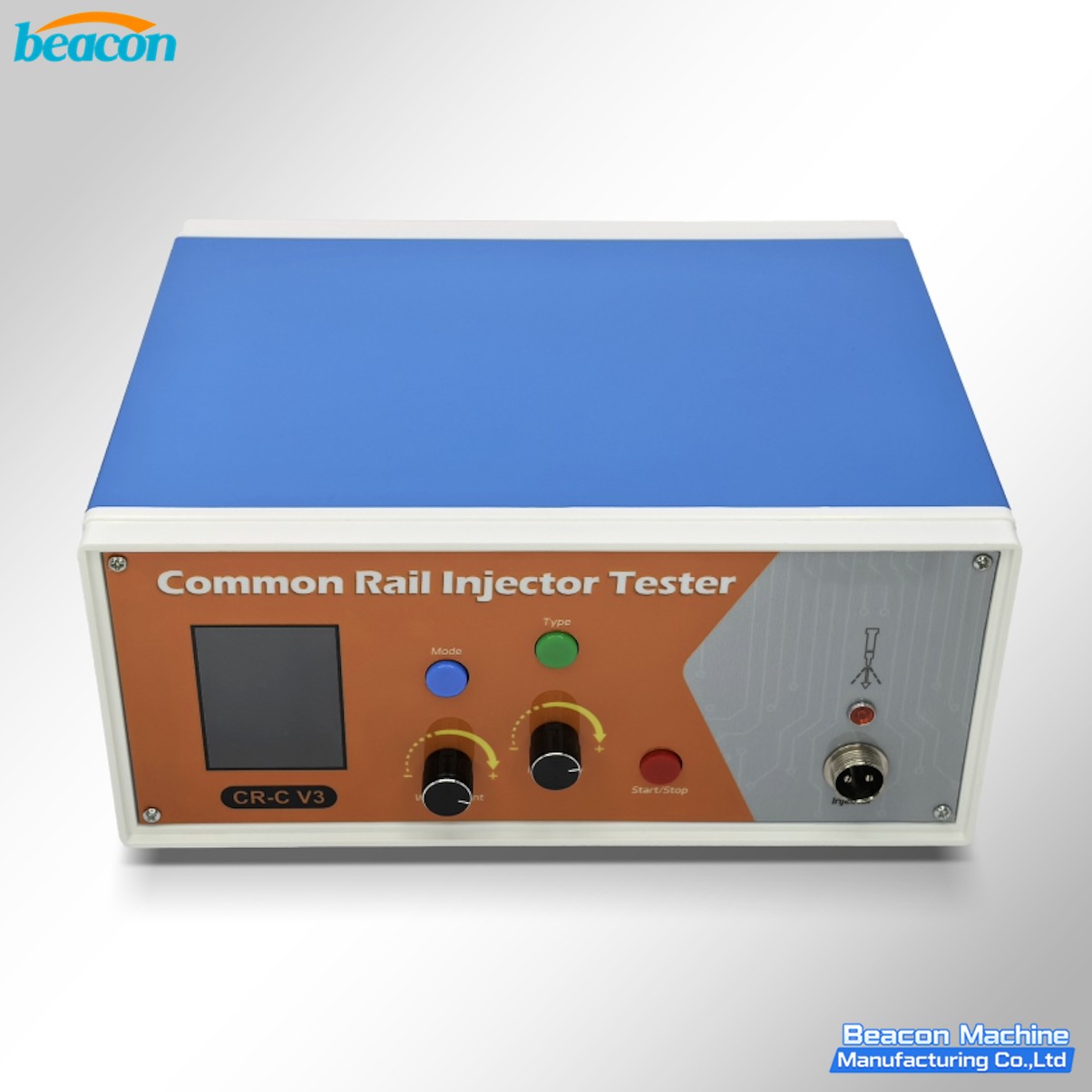
CR-C V3 Common Rail Injector Tester for Solenoid and Piezo Injectors
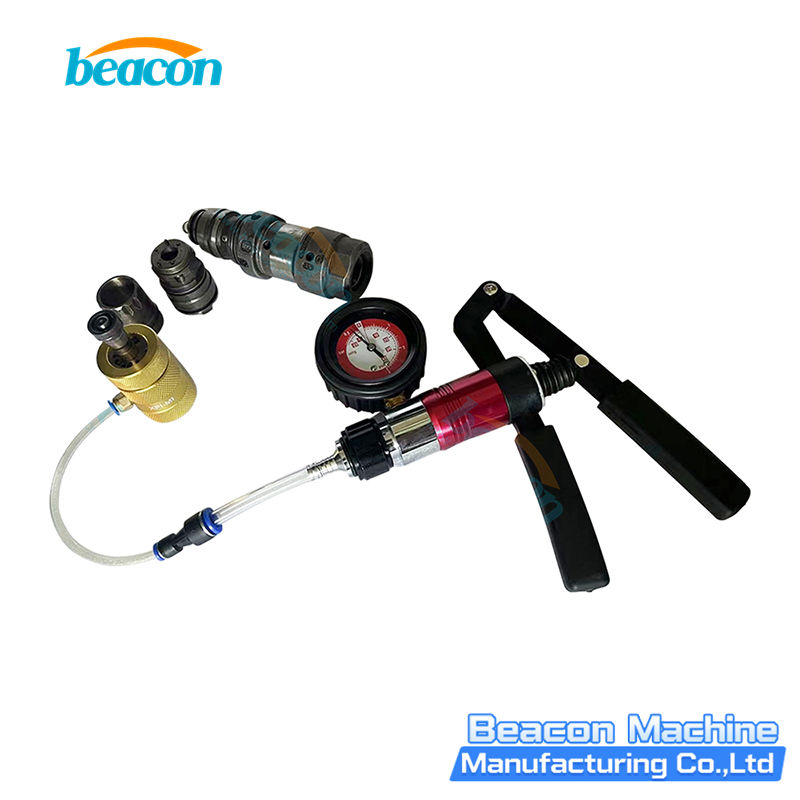
G4-55 Cummins Q60 Nozzle Leakage Test Tool - Fuel Injector Nozzle Seal Tester for Q60 Engine

EPS212 Common Rail Injector Test Bench
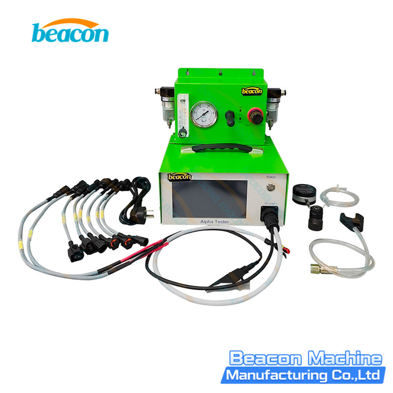
CRI350 Piezo Injectors Full-Functional Tester for Bosch Denso Siemens VDO
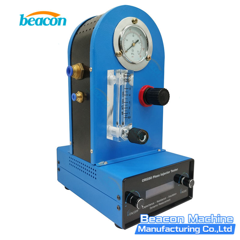
CRI250 Piezo Injector Comprehensive Tester Resistance Capacitance Dynamic Lift Measurement

CR918-PRO Full Function Common Rail HEUI EUI EUP Test Bench with 4 Tanks

Beacon CR819S All-Function Common Rail Injector, Pump, EUI/EUP & HEUI Test Bench
Beacon Machine Manufacturing Co.,ltd
Quick Links
contact
WhatsApp: +86-13570429157
Tel / Wechat: 0086-13570429157
Email: ellenzhang@beacon-machine.com
Add: High Technology Industrial Park of Taian city,Shandong province,China


quick order
We will reply to your email within 2 hours