
Beacon Machine Manufacturing Co.,ltd
 Language
  EN
EN RU
RU ES
ES DE
DE EL
EL IT
IT JA
JA KO
KO PT
PT ID
ID SR
SR UK
UK VI
VI TH
TH TR
TR MS
MS BE
BE AR
ARCommon Rail Pump Cannot Build Pressure: Causes and Step-by-Step Diagnosis
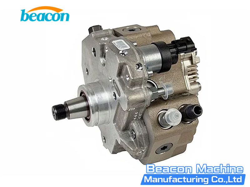
When a common rail diesel engine has a long crank, fails to start, loses power or stores a rail-pressure fault code, the high-pressure pump is often suspected first. Low rail pressure identifies a system-level fault; several components can produce the same symptom.
Rail pressure depends on low-pressure fuel supply, pump output, metering control and every possible high-pressure loss. A restricted supply, trapped air, excessive injector return flow, a leaking pressure-control device, incorrect sensor data or an internal pump fault can all prevent pressure from reaching the specified value.
- 1. Is the pump inlet receiving the fuel supply required by the application?
- 2. Is fuel escaping through an excessive high-pressure or return-side leak?
- 3. Can the metering system and mechanical pumping elements operate correctly?
Important: Cranking pressure, feed pressure, valve-control strategy and test conditions vary by engine and pump. Use the current service information for the exact vehicle and the test plan for the complete pump part number.
1. What Does “Cannot Build Pressure” Mean?
The common rail pump compresses fuel and supplies the rail. The rail stores high-pressure fuel for electronically controlled injection. DENSO explains that the pump creates the required pressure at the required time and supplies pressurized fuel to the common rail system. DENSO common rail pump operation
A pressure-building fault may appear as slow pressure rise during cranking, actual pressure below the application requirement, pressure that rises and then falls, a persistent gap between commanded and actual rail pressure, or a pump that fails delivery or pressure points on a test bench. Each pattern directs diagnosis; none identifies the pump as the sole cause.
2. Main Causes of Insufficient Rail Pressure
2.1 Insufficient Low-Pressure Fuel Supply
The high-pressure pump needs a stable, air-free inlet supply at the pressure or flow specified for the application. A blocked fuel filter, weak transfer pump, restricted or kinked line, leaking connector, tank pick-up problem or tank-vent fault can limit inlet fuel. Bosch treats low- and high-pressure measurements as separate parts of a complete common rail diagnosis. Bosch Common Rail System Diagnosis
- Check fuel level and fuel quality.
- Inspect the filter and the supply line.
- Measure inlet pressure or flow at the specified location.
- Check the transfer pump, connectors, seals and tank ventilation.
2.2 Air Trapped in the Fuel Circuit
Air is compressible. After a filter, pipe, pump or injector has been removed, incomplete priming can slow pressure build-up and make results unstable. Complete the application-specific bleeding and pre-supply procedure before judging the pump. Extended cranking is not a substitute for the specified bleeding procedure.
2.3 Excessive Injector Return Flow
Fuel delivered to the rail can escape through excessive internal injector leakage. Delphi recommends injector back-leakage measurement before condemning the common rail pump. Delphi common rail diagnostic procedure
Compare every injector under the same test condition and use the limit specified for the application. One leaking injector can prevent the complete system from reaching the required cranking pressure.
2.4 Leaking Rail Pressure-Control or Limiting Valve
A pressure-control valve, pressure-limiting valve or another rail-control device may release too much fuel to return when it cannot seal correctly. Bosch describes the pressure-control valve as the component that precisely controls rail pressure and the limiting valve as a rail-matched safety component. Bosch rail and pump components
Inspect these devices only with the prescribed procedure. Improvised plugs and uncontrolled outlet blocking are unsafe.
2.5 Metering Valve or Suction Control Valve Fault
The pump metering device may be called an IMV, MPROP, SCV or metering unit. It controls how much fuel enters the pumping elements. DENSO states that the SCV regulates the fuel pumped into the common rail system to maintain consistent pressure. DENSO SCV operation and types
- Contamination or valve sticking;
- coil open circuit or short circuit;
- poor connector contact;
- power, ground or control-circuit fault;
- incorrect or mismatched valve.
DENSO also documents normally open and normally closed SCVs for HP3 and HP4 applications. Their de-energized behavior is different. A universal “disconnect the valve” test or direct voltage test can produce a wrong conclusion or damage.
2.6 Rail Pressure Sensor or Wiring Fault
The rail-pressure sensor continuously monitors high-pressure fuel and sends the value to the engine control unit. Bosch common rail system components
Check fault codes, reference voltage, ground, signal wiring and plausibility according to the vehicle circuit diagram. When the service procedure permits an independent pressure measurement, compare it with scan-tool data. A sensor or wiring fault can distort the displayed value and affect pressure control.
2.7 Internal Mechanical Wear or Leakage in the Pump
After inlet supply, system leakage and electronic control have been checked, investigate the mechanical pump. Possible areas include high-pressure pumping elements, internal seals, valve seats, plunger movement, cam or eccentric mechanisms and the pump housing.
Bosch identifies mechanical housing damage, failed seals and wear in the high-pressure area as causes of leakage, imprecise delivery, insufficient pressure, starting problems and pump failure. Bosch common rail pump wear and failure risks
2.8 Fuel Contamination or Water
Particles can cause wear or sticking in precision components. Water can corrode metal surfaces and reduce lubrication between moving parts. Delphi states that water contamination can cause premature wear of injectors and the high-pressure pump. Delphi contamination and service advice
If metal particles, water or severe contamination are found, follow the vehicle manufacturer’s contamination procedure for the tank, lines, rail, valves and injectors. The required repair scope is application-specific.
2.9 Incorrect Pump Identification, Installation or Drive Conditions
Confirm the complete pump part number, rotation direction, drive connection, actual speed, valve type, inlet and return ports, adapters and current test-plan version. A similar-looking pump, valve or program can create an invalid result.
3. Step-by-Step Diagnostic Procedure
Step 1: Record the Original Fault Data
Save all fault codes and freeze-frame information. Record cranking speed, commanded and actual rail pressure, available low-pressure data, actuator commands and recent fuel-system work. Preserve the pressure-rise sequence instead of keeping only one value.
Step 2: Inspect Fuel, Filter and Contamination
Check that the correct fuel is present. Inspect the filter sample for water, particles, metal debris, unusual color or deposits. Identify the contamination source before installing replacement parts.
Step 3: Test the Low-Pressure Circuit
Measure supply pressure or flow at the location and operating condition specified by the manufacturer. Check the transfer pump, filter restriction, pipe routing, connectors, seals, priming and tank ventilation. Repair an inadequate inlet supply before high-pressure diagnosis continues.
Step 4: Validate Rail Pressure Data
Compare commanded and actual rail pressure and test the sensor circuit from the application wiring diagram. Use only approved high-pressure equipment if an independent pressure comparison is required. A general-purpose gauge is unsuitable for a common rail system.
Step 5: Measure Injector Return and High-Pressure Leakage
Measure every injector under the same condition. Check the rail pressure-control device, pressure-limiting valve, high-pressure pipes, rail and pump-to-rail circuit as directed by the manufacturer. Delphi’s sealed-rail approach combines pump-pressure checking with injector back-leakage measurement to isolate the fault area. Delphi Sealed Rail Diagnostic Kit
Step 6: Check the Metering Valve and Its Control Circuit
Identify the exact valve and whether its operating strategy is normally open or normally closed. Check coil and insulation condition, power, ground, command signal, connector condition and pressure response using the correct specifications. Do not transfer resistance, duty-cycle or voltage values from another pump family.
Step 7: Perform an Approved Pump-Isolation Test
Where the vehicle and test-equipment procedure permits, a dedicated sealed-rail and false-actuator test can separate pump output from injector leakage and the original actuator. Pressure that returns to specification with the approved false actuator points toward the vehicle actuator or its control. Pressure that remains low increases suspicion of a mechanical pump fault. This test requires the system-specific tool and procedure.
Step 8: Confirm Pump Performance on a Test Bench
If vehicle-side diagnosis points to the pump, remove it and use the exact test plan. Confirm pump number, adapter, rotation, speed, test fluid and temperature, inlet condition, metering-valve drive, pressure, delivery, return and leakage points.
Workshops that test common rail pumps and other diesel injection components can use the Beacon CR919 multifunctional diesel test bench. The product page confirms common rail pump testing capability; acceptance limits must still come from the exact pump test plan.
Step 9: Complete a Full Post-Repair Verification
After repair or replacement, repeat low-pressure supply, bleeding, pressure build-up, commanded-versus-actual tracking, injector return, control-valve operation, leakage and fault-code checks. Apply the manufacturer’s complete system-cleaning procedure when contamination caused the failure.
4. Result Patterns and Priority Checks
| Observed Result | Priority Diagnostic Direction |
|---|---|
| Pump inlet pressure or flow is below specification | Tank, transfer pump, filter, supply lines, connectors and air ingress |
| Rail pressure is low and one injector exceeds its return-flow limit | Internal leakage in that injector |
| Pressure-control or limiting-valve return is abnormal | Valve, seat and control circuit |
| Pressure returns with an approved false actuator | Original metering actuator, connector, wiring or command signal |
| Pressure remains low during an approved isolated-pump test | Mechanical pump fault becomes more likely |
| Scan data shows low pressure but approved independent measurement is normal | Rail-pressure sensor, wiring or data plausibility |
| Bench results change between repeated runs | Bleeding, inlet supply, temperature, speed, drive signal or internal sticking |
| Pump passes the correct bench plan but vehicle pressure remains low | Vehicle supply, system leakage, injector return, rail valves, sensor or control system |
Use the limits assigned to the exact application and pump test plan. These patterns organize diagnosis; they do not replace manufacturer procedures.
5. Diagnostic Practices That Cause Wrong Conclusions
Replacing the Pump from a Low-Rail-Pressure Code Alone
A fault code defines the affected system. Test inlet supply, leakage, return flow, control devices and sensor data before deciding which component failed.
Using One Universal Cranking-Pressure Limit
Minimum starting pressure and its test condition vary by engine and control system. Apply the exact vehicle specification.
Disconnecting or Directly Energizing the Metering Valve
Normally open and normally closed valves react differently. Follow the pump-specific electrical and hydraulic procedure.
Judging the Pump from One Pressure Point
A complete pump evaluation may include several speeds and control points plus delivery, return, leakage, stability and response.
Installing a Pump Without Correcting Contamination
Remaining water or particles can damage the replacement pump and other precision components. Complete the manufacturer’s prescribed system treatment.
6. Frequently Asked Questions
Does low rail pressure prove that the pump plungers are worn?
No. Inadequate inlet supply, air, excessive injector return, a leaking control device, metering-valve trouble and incorrect sensor data can create the same symptom.
Can all injector outlets be blocked to test the pump?
Use only an approved sealed-rail or system-specific method. Improvised plugs and uncontrolled outlet blocking create a serious high-pressure hazard.
Why can a pump pass on the bench while the vehicle still has low pressure?
The vehicle may still have a low-pressure supply problem, excessive injector return, a leaking rail valve, a sensor or wiring fault, air in the circuit or incorrect electronic control.
Should the pump be retested after replacing the metering valve?
Yes. The metering valve directly affects fuel quantity and pressure control. Run the complete pump-specific test plan rather than checking only one pressure point.
Conclusion
Insufficient rail pressure is a system-level result. Reliable diagnosis follows a fixed sequence: record the fault, inspect fuel and contamination, test low-pressure supply, validate pressure data, measure injector return and high-pressure leakage, check metering control, perform an approved pump-isolation test and confirm the pump on a test bench.
A mechanical pump diagnosis becomes well supported after inlet supply, system leakage, pressure regulation and electrical control have been tested. This sequence reduces unnecessary parts replacement and protects a repaired or replacement pump from an unresolved system fault.
Safety: Common rail fuel can penetrate skin and cause fatal injury. Never search for a leak by hand, loosen a high-pressure connection while the system is operating or pressurized, or use unapproved fittings and plugs. Follow the vehicle, component and test-equipment manufacturers’ procedures.
Related products
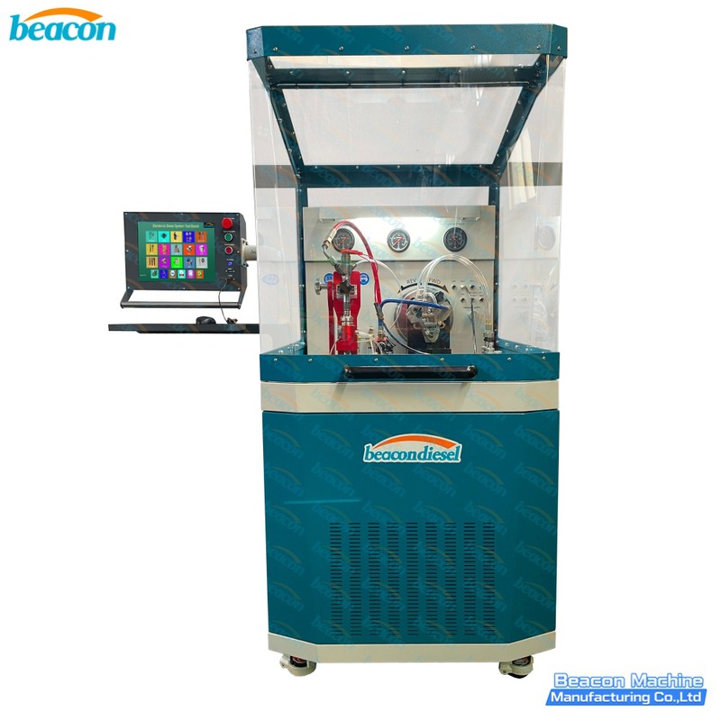
BC810 Common Rail Diesel Injector and Pump Test Bench
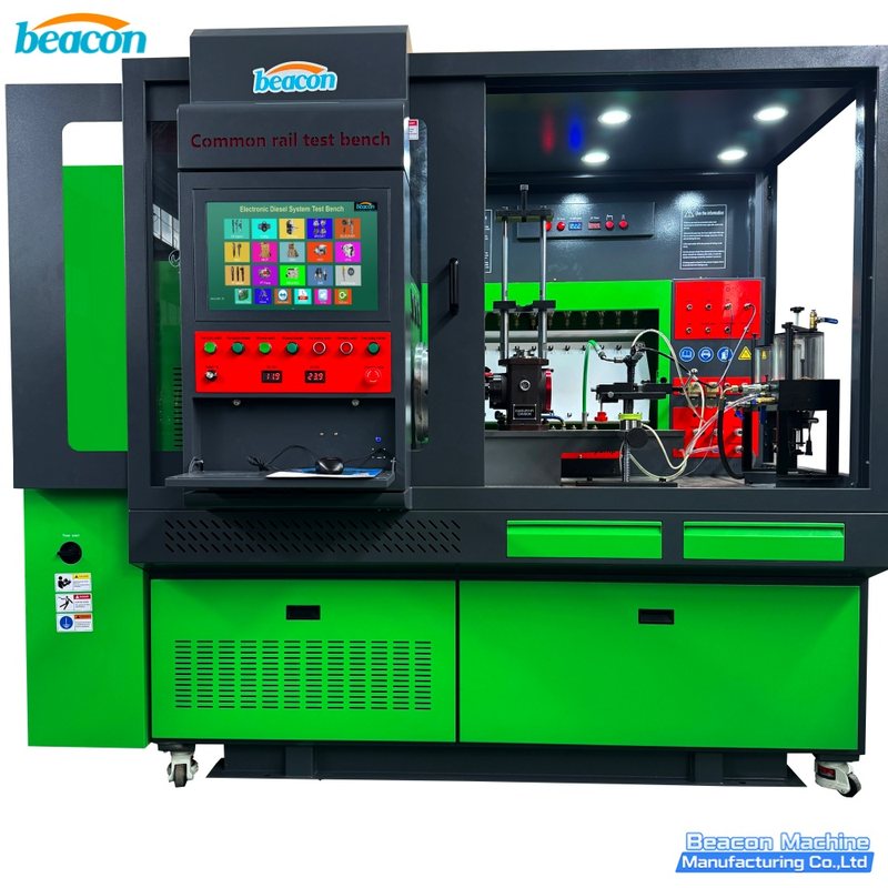
CR919PLUS Common Rail Injector and Pump Test Bench
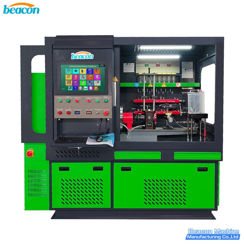
CR910 Common Rail Injector and Pump Test Bench
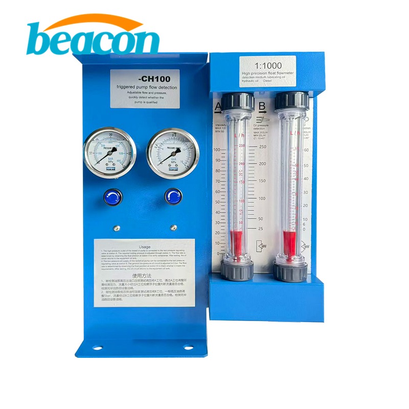
G10-31 HEUP Pump Flow & Pressure Tester
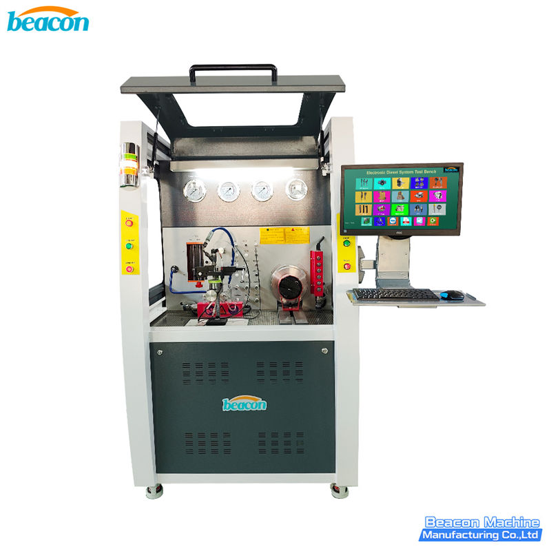
CR1029 High Pressure Common Rail Comprehensive Performance Test Bench - CR Injector & Pump Tester
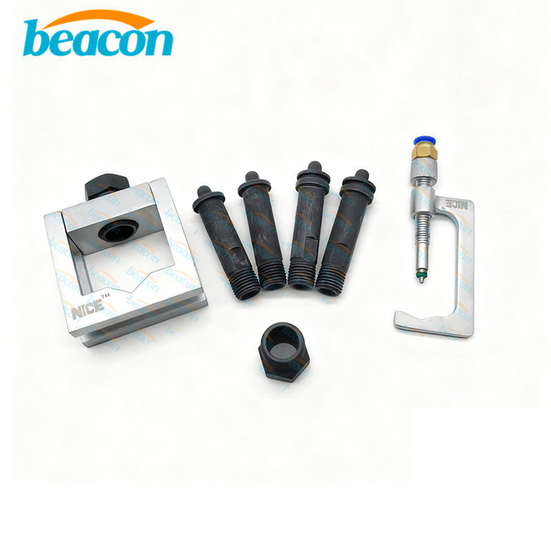
G2-4 Simple Universal Clamp - Universal Injector Pump Holder
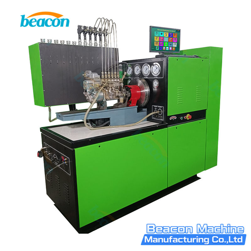
EPS816 Diesel Injection Pump Test Bench
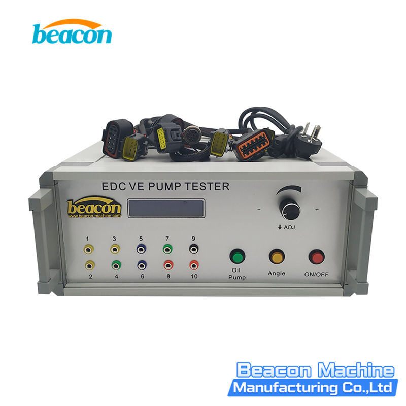
EDC VE/VP Pump Tester / Simulator for VP37 Electronic Diesel Pumps
Beacon Machine Manufacturing Co.,ltd
Quick Links
contact
WhatsApp: +86-13570429157
Tel / Wechat: 0086-13570429157
Email: ellenzhang@beacon-machine.com
Add: High Technology Industrial Park of Taian city,Shandong province,China


quick order
We will reply to your email within 2 hours