
Beacon Machine Manufacturing Co.,ltd
 Language
  EN
EN RU
RU ES
ES DE
DE EL
EL IT
IT JA
JA KO
KO PT
PT ID
ID SR
SR UK
UK VI
VI TH
TH TR
TR MS
MS BE
BE AR
ARCommon Rail Injector Passes Bench Test but Engine Still Runs Rough: 8 Possible Causes
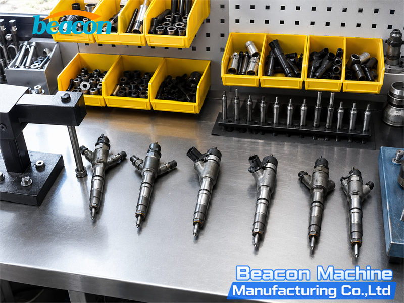
A common rail injector can pass a bench test and still be followed by rough idle, knocking, smoke, misfire, or poor power after installation. This does not automatically mean that the test bench was wrong, and it does not prove that the injector is fault-free under every condition.
A bench report confirms how the injector performed with a specific test plan, rail pressure, energizing time, calibration fluid, temperature, and measurement system. The engine, however, also depends on injector coding, installation quality, vehicle wiring, rail-pressure control, air management, and mechanical condition. DENSO explains that common rail operation depends on precise control of injection pressure, timing, rate, and quantity. A fault anywhere in that chain can change engine behavior.
1. The Injector or Test Plan Was Identified Incorrectly
Always identify the injector by its complete part number. Do not select a test plan only from appearance, engine family, or a similar number. Injectors in the same physical family may use different calibration limits, control strategies, or applications. A visually similar program can therefore produce a misleading pass result.
As of 2026, the database used with Beacon common rail test benches contains more than 8,200 injector data records covering multiple major brands, more than 1,800 common rail pump data records, and nearly 800 EUI/EUP data records. A large database improves coverage, but it does not replace correct selection. The technician must still match the full part number, application, injector type, and required test plan.
Before accepting a result, confirm:
- the brand and complete part number on the injector;
- solenoid, piezo, or other applicable technology;
- the correct and current test-plan version;
- the correct adapter, return connection, cable, and drive mode;
- that the part number shown on the report matches the component tested.
Bosch highlights regular online updates to current test specifications for its DCI platform, while Hartridge states that its test plans are developed for specific injectors and applications. Correct plan selection is therefore the first condition for a valid result.
2. Only Some Test Points Passed, or Test Conditions Were Unstable
A common rail injector should not be judged from one operating point. An injector may appear acceptable at a high-delivery point but fail at idle, pilot injection, minimum drive pulse, leakage, or another required condition. Small-delivery behavior is particularly relevant to idle quality, combustion noise, and emissions.
Hartridge distinguishes a rapid functional check from a repair-quality evaluation and lists separate checks such as nozzle opening pressure and minimum drive pulse. The correct conclusion is therefore not simply “the injector injected fuel,” but “the injector passed every mandatory point in the applicable test plan.”
Verify that:
- the calibration fluid and temperature met the equipment and test-plan requirements;
- air was removed from the high-pressure and measuring circuits;
- rail pressure and return back pressure were stable;
- the measuring system, sensors, and bench were within calibration;
- adapters and high-pressure or return connections did not leak;
- abnormal or borderline points were repeated and produced consistent results.
There is no universal flow, temperature, resistance, or timing limit for every injector. Always use the specification for the exact part number and test program.
3. The New Injector Correction Code Was Not Written Correctly to the ECU
Many modern common rail injectors use a correction code to compensate for manufacturing and repair-related variation. Depending on the system, the code may be called IMA, IQA, C2i, C3i, QR, or another manufacturer-specific name.
Beacon test systems support injector coding for supported Bosch, Denso, Delphi, Siemens/Continental, and other applicable injector programs. After repair, the newly generated code must be recorded accurately and written to the correct cylinder in the vehicle ECU when the vehicle manufacturer requires it.
Delphi states that a new C2i/C3i code is critical after an injector has been repaired and recalibrated. If the new code is not entered, poor running, idle problems, and diagnostic trouble codes may result.
Check the following:
- use the new post-repair code rather than the old code;
- enter every character accurately;
- assign each code to the correct cylinder;
- perform any injector learning or adaptation required by the vehicle manufacturer;
- read the data back from the ECU to confirm that it was stored.
Coding cannot repair mechanical wear or turn a failed injector into a good one. It allows the ECU to compensate for the measured characteristics of an injector that has already passed the correct test procedure.
4. Installation, Sealing, or High-Pressure Pipework Is Incorrect
An injector that passed on the bench can still cause trouble if it is not sealed correctly in the cylinder head. Delphi notes that a missing or incorrectly seated nozzle washer can allow combustion residue to pass the seal, while seal rings can move out of their grooves during installation. Perkins also identifies poor sealing in the cylinder head, two sealing washers, and incorrect injector installation as possible causes of uneven running or misfire.
After installation, inspect:
- whether the old copper washer was completely removed;
- whether the injector seat is clean, flat, and undamaged;
- whether the correct new washer and seals were fitted;
- whether the clamp, bolt, and high-pressure pipe were installed to vehicle specifications;
- whether the return connector is damaged or leaking;
- whether combustion gas, carbon, or fuel is visible around the injector.
Do not use a universal torque value. Fasteners, procedures, and high-pressure pipe replacement rules differ by engine and must follow the vehicle manufacturer's service information.
5. The Vehicle Wiring, Connector, or ECU Driver Is Faulty
A bench may verify the injector's own coil, insulation, or response, but it cannot prove that the vehicle harness, connector, power supply, ground, or ECU output is correct. On the bench, the injector is driven by the tester. On the engine, it is controlled through the vehicle's complete electrical circuit.
Follow the correct wiring diagram and check:
- injector circuit fault codes and freeze-frame information;
- loose, corroded, oil-contaminated, or backed-out connector pins;
- harness damage caused by heat, vibration, abrasion, or crushing;
- continuity, insulation, and voltage drop according to OEM procedures;
- the ECU injector command waveform when the specified equipment and procedure are available;
- whether the fault appears only with vibration or temperature change.
Do not apply a generic resistance threshold to every injector. Solenoid and piezo systems, and even different families within one brand, require different procedures.
6. Low-Pressure Supply or Rail-Pressure Control Is Incorrect
A good injector cannot operate correctly without stable fuel supply and rail pressure. A restricted filter, air entering the supply circuit, a weak high-pressure pump, excessive return from another injector, or a fault in the SCV/IMV, DRV, or rail-pressure sensor can cause actual rail pressure to differ from the ECU target.
Delphi recommends checking injector back leakage and rail pressure together, then distinguishing a mechanical pump problem from an inlet metering or pressure-control fault.
Compare:
- target and actual rail pressure during cranking, idle, and the fault condition;
- low-pressure supply pressure and flow against vehicle specifications;
- fuel-filter condition and evidence of air or contamination;
- return flow from the complete injector set;
- high-pressure pump, metering valve, pressure-control valve, and sensor behavior;
- whether rail-pressure fluctuation occurs at the same time as rough running.
7. The EGR, Intake, or Boost System Is Disturbing Combustion
Rough idle and smoke are not unique to injector faults. An EGR valve stuck in the wrong position, restricted intake passages, incorrect air-mass measurement, boost leakage, or implausible MAP/MAF data can change the air available for combustion.
Delphi states that an EGR valve stuck open can cause reduced power, poor acceleration, and rough idle. Diagnosis should combine fault codes, actuator tests, electrical checks, and inspection for carbon restriction rather than replacing parts from symptoms alone.
Review:
- commanded and actual EGR position;
- air-mass and intake-pressure data;
- commanded and actual boost pressure;
- intake hoses, charge-air pipes, and intercooler leakage;
- EGR valve and intake-passage contamination;
- air-filter restriction and sensor plausibility.
8. Engine Mechanical Condition or Synchronization Is Incorrect
If the fuel, electrical, and air systems check correctly, confirm that each cylinder can burn the delivered fuel. Low compression, valve leakage, worn rings or liners, mechanical timing error, or an abnormal crankshaft/camshaft synchronization signal can reduce cylinder contribution even when the injector itself is satisfactory.
Bosch diesel diagnostic training treats cylinder balance, crankshaft and camshaft signals, engine synchronization, air quantity, EGR, boost, and relative compression as related parts of the diagnostic process. Begin with cylinder-balance or contribution data, then perform relative or mechanical compression testing according to the engine manufacturer's procedure.
Do not condemn an injector only because the ECU shows a large cylinder correction value. That correction may also be a response to compression, air-path, or other combustion differences.
A Practical Diagnostic Sequence
| Step | What to Check | Purpose |
|---|---|---|
| 1 | Record whether the fault occurs cold, hot, at idle, during acceleration, or under load | Reproduce the actual complaint |
| 2 | Read DTCs, freeze frame, cylinder balance, target rail pressure, and actual rail pressure | Identify the affected system |
| 3 | Verify complete injector number, test plan, test conditions, and full report | Confirm the bench result is valid |
| 4 | Verify correction codes, cylinder assignment, and required adaptation | Confirm correct ECU calibration |
| 5 | Inspect seat, seals, return connections, and high-pressure pipes | Exclude installation faults |
| 6 | Test connector, wiring, and ECU command | Exclude vehicle electrical faults |
| 7 | Test supply pressure, rail-pressure control, EGR, airflow, and boost | Evaluate the surrounding systems |
| 8 | Check synchronization, cylinder contribution, and compression | Confirm mechanical combustion conditions |
For workshops that test both common rail injectors and high-pressure pumps and may also handle EUI/EUP or HEUI work, the CR1017 multifunction common rail pump and injector test bench provides a combined component-testing platform. A component bench, however, does not replace on-vehicle ECU diagnosis, wiring checks, rail-pressure analysis, air-system inspection, or compression testing.
Conclusion
“Passed the bench test” is important evidence, but it is not a diagnosis of the complete engine. A reliable conclusion requires three questions to be answered:
- Was the injector tested with the correct, complete, and repeatable procedure?
- Was it coded, installed, sealed, and electrically driven correctly?
- Are fuel pressure, air management, synchronization, and mechanical condition correct?
Combining the component report with live vehicle data prevents repeated removal, unnecessary injector replacement, and avoidable repair cost.
Safety: Common rail systems operate at pressures capable of causing fatal injection injury. Never use a hand to search for leakage, loosen a high-pressure line while the engine or bench is running, or use improvised fittings and containers. Follow the vehicle and equipment manufacturer's safety procedures.
Technical basis: this article was cross-checked against official technical information from Bosch Mobility Aftermarket, Delphi/Hartridge, DENSO, and Perkins. All application-specific limits and procedures must follow the original injector, test-equipment, and vehicle manufacturer data.
Related products
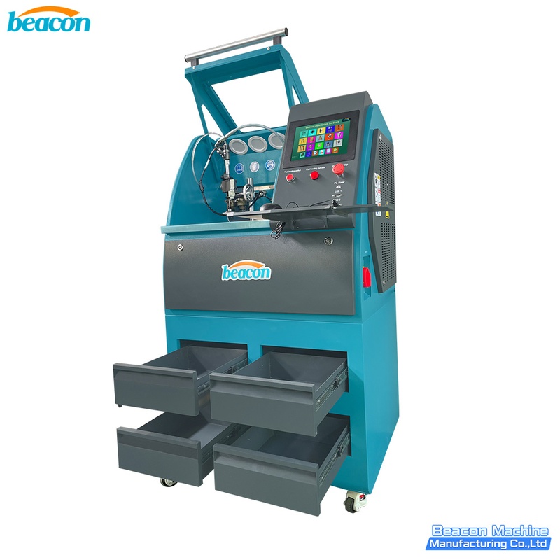
EPS206 PLUS Common Rail Injector Test Bench | Piezo & Coding
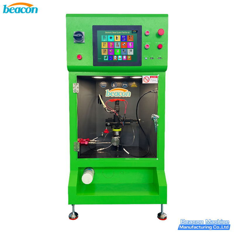
EPS290 Common Rail Injector Test Bench
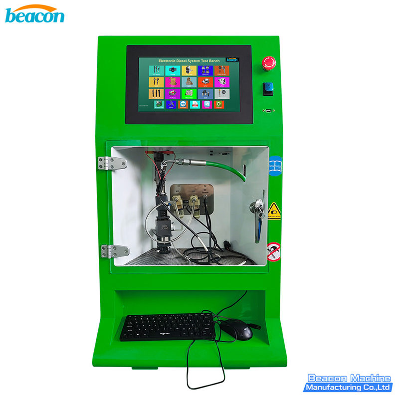
EPS212 Common Rail Injector Test Bench

CR918-PRO Full Function Common Rail HEUI EUI EUP Test Bench with 4 Tanks
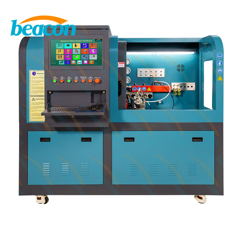
Beacon CR819S All-Function Common Rail Injector, Pump, EUI/EUP & HEUI Test Bench
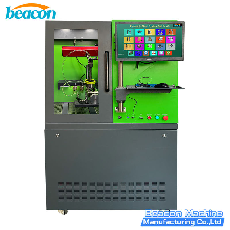
Beacon BC200-PRO Common Rail Injector Test Bench

Beacon EPS106 Common Rail Injector Tester – Professional Test Bench for Solenoid & Piezo Injectors
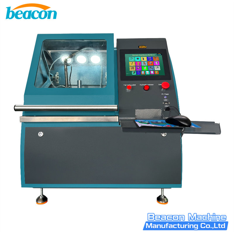
Beacon EPS206-PRO Common Rail Injector Test Bench | Coding & Piezo Testing
Beacon Machine Manufacturing Co.,ltd
Quick Links
contact
WhatsApp: +86-13570429157
Tel / Wechat: 0086-13570429157
Email: ellenzhang@beacon-machine.com
Add: High Technology Industrial Park of Taian city,Shandong province,China


quick order
We will reply to your email within 2 hours